GND in a Circuit: Definition and Essential Functions
You often see the term GND in a circuit. GND stands for ground, which acts as your zero-volt reference point and provides a common return path for current. When you ask what is gnd in a circuit?, you look at the point where all voltages get measured. You need GND because it keeps your circuit safe and stable. For example, ground connections like earth ground and chassis ground protect you from electrical shock by giving current a low-resistance path. GND in a circuit also helps your devices work right by completing the path for current.
Key Takeaways
GND means ground and is the zero-volt point in a circuit. It helps us measure voltage correctly. A good ground connection finishes the circuit. It gives a safe way for current to go back. This lets devices work as they should. There are different types of ground. These include signal ground, power ground, digital ground, and earth ground. Each type has a special job to keep circuits safe and steady. Earth ground links circuits to the real earth. This keeps people and equipment safe from shocks and problems. Good grounding cuts down noise and stops interference. This makes circuits work better and keeps them from breaking. Some common grounding mistakes are floating grounds, ground loops, mixing grounds the wrong way, and high resistance in the path. These mistakes can cause problems in the circuit. Using a star ground layout and thick, short wires keeps ground resistance low. This also stops loops and noise. You should plan and check your ground connections before turning on your circuit. This keeps things safe, correct, and working well for a long time.
What Is GND in a Circuit?

What Is GND?
Every circuit has a spot called GND. This spot is where electric current goes back. When you ask, "what is gnd in a circuit?", you want to know where all voltages are checked. GND means ground. It links parts of your circuit and lets current return to the source. If you do not have a good ground, your circuit will not work right. Knowing what is gnd helps you make safe and strong circuits.
GND is also used as a voltage reference. All voltages in your circuit are checked from this spot. If you want to know how gnd works, think of it as the anchor for your circuit. It keeps voltages steady and helps you measure them right. When you connect your circuit to ground, you give current a safe way to go back.
GND as Zero-Volt Reference
GND is the zero-volt reference in every circuit. You use this spot to compare all other voltages. When you check voltage anywhere, you always check it from ground. That is why people call it the ground reference. GND gives you a steady spot to measure from and helps you avoid mistakes.
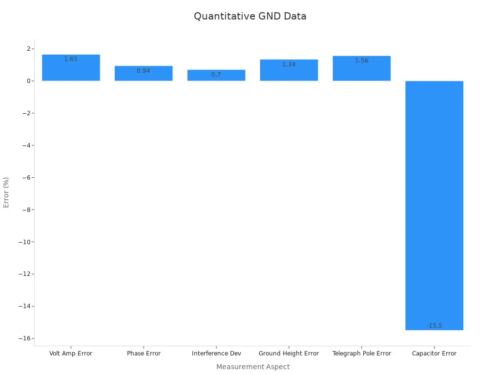
Good voltage checks need a good ground. If your ground is not steady, your numbers can be wrong. Studies show that with good grounding, the biggest voltage error is only 1.65%. The phase error drops to 0.94%. Even if you move your sensor up or farther from a telegraph pole, the error stays under 1.56%. This means your circuit stays correct and works well.
Measurement Aspect | Quantitative Result | Description |
|---|---|---|
Maximum relative error of voltage amplitude | 1.65% | High accuracy in voltage amplitude measurement with proper grounding. |
Phase relative error | 0.94% | Precise phase measurement under proper grounding conditions. |
Maximum deviation with/without interference | 0.7% | Equipotential shielding reduces interference effects. |
Maximum percentage error with varying ground height (h1) | 1.34% | Measurement accuracy remains stable despite changes in sensor height to ground. |
Maximum percentage error with varying distance to telegraph pole (d1) | 1.56% | Measurement accuracy remains stable despite changes in sensor distance to telegraph pole. |
Calibration error due to capacitor accuracy (0.01%) | Up to -15.5% error without optimization | Parameter optimization reduces error propagation. |
Simulated sensor output voltage error (0.5%) | Calibration error curves show impact on accuracy | Reducing certain capacitances improves accuracy. |
Tip: Always check your ground before you measure voltage. A bad ground can cause big mistakes.
GND Symbols and Notation
You will see different GND symbols in circuit diagrams. The most common one looks like three short lines stacked. Sometimes, you see a triangle pointing down or a line with three short lines under it. Each symbol means a ground connection, but they can mean different types, like earth ground or chassis ground.
Here are some GND symbols you might see:
Three short lines stacked
Triangle pointing down
Line with three short lines under it
You should always look at the legend or notes in your diagram. This helps you know what type of ground each symbol means. Using the right symbol makes your circuit easier to read and safer to build.
Why Do You Need a GND?
Circuit Completion
You need a ground in every circuit to make it work. The ground gives current a way to return to the power source. If you leave out the ground, your circuit cannot complete the loop. No current will flow, and your devices will not turn on. This is the basic working principle of gnd.
GND acts as a stable reference point, usually at 0 volts.
It completes the circuit by letting current flow back to the source.
Every part in your circuit uses ground as a common point.
GND helps reduce unwanted signals and interference.
When you connect the ground, you make sure your circuit works as planned. You can see this in datasheets and technical reports. They always show a ground connection to finish the path for current. If you ever wonder why do you need a gnd, remember that without it, your circuit stays open and useless.
Tip: Always check that your ground connections are solid before you power up your circuit.
Voltage Reference
Ground does more than just complete the circuit. It also gives you a steady spot to measure voltages. You use ground as your main reference point. This is called the ground reference. When you measure voltage at any point, you compare it to ground. This makes your readings clear and easy to understand.
GND provides a common zero voltage potential.
It lets you compare voltages across different parts of the circuit.
Using ground as a reference keeps your measurements accurate.
If you skip the ground reference, your voltage numbers can jump around. You might get wrong readings, which can lead to mistakes in your design. The working principle of gnd means you always have a trusted spot to check voltages. This is why do you need a gnd in every project.
Safety Role
Ground keeps you safe when you work with circuits. It gives extra current a safe path to the earth. If something goes wrong, like a short circuit, ground helps carry the fault current away from you. This lowers the risk of electric shock.
GND grounds excess electrical charges.
It offers a safe discharge path to earth.
Ground prevents electrical shocks and safely handles fault currents.
It helps shield your circuit from electromagnetic and radio-frequency interference.
Many devices use different types of ground, such as earth ground or chassis ground, to boost safety. You can see these in power supplies, computers, and home wiring. A good ground connection protects both you and your equipment. Always make sure your ground is secure before you start working.
Safety Feature | How Ground Helps |
|---|---|
Shock Prevention | Directs fault current to earth |
Equipment Protection | Shields against surges |
Noise Reduction | Blocks unwanted interference |
Note: Never ignore the ground in your circuit. It is your first line of defense against hazards.
GND Types

When you work with circuits, you will find different ground types. Each type has its own job. Knowing the classification of gnd helps you make safer circuits. Let’s see the main types you will use in most systems.
Signal Ground
Signal ground is where signals in your circuit are measured. You use this ground for small signals, like in audio or sensor circuits. Signal ground keeps signals clean and stops noise. If you mix signal ground with other types, you can get errors or interference.
Signal ground is a quiet path for sensitive signals.
It helps you control input signals and makes your system better.
You see signal ground in analog circuits, where you need accuracy.
Tip: Keep signal ground away from power ground to stop noise.
Power Ground
Power ground is for the return path of big currents. You use this ground for motors, power supplies, or parts that need lots of energy. Power ground must be strong and carry high currents without voltage drops. If you do not use the right power ground, your circuit can have problems.
Power ground connects to the negative side of your power supply.
It keeps voltage steady in your system.
You see power ground tied to the metal case or chassis in big machines.
Here is a simple table that shows the difference between signal ground and power ground:
Type | Main Use | Key Feature |
|---|---|---|
Signal Ground | Small, sensitive signals | Reduces noise and interference |
Power Ground | High current devices | Handles large return currents |
Digital Ground
Digital ground is for circuits with digital signals, like computers or microcontrollers. Fast switching in digital circuits makes a lot of noise. Digital ground gives these signals a safe way back to the source. This helps your digital devices work right and lowers errors.
Digital ground keeps noise away from digital parts of your circuit.
It makes signals better and keeps your data correct.
You see digital ground marked as DGND in circuit diagrams.
Technical manuals list these types in the classification of gnd. You will also find other types, like earth ground and chassis ground, which you will learn about next. Each type helps keep your circuit safe, stable, and correct.
Note: Always check your circuit diagram to know which ground type to use. Mixing them can cause trouble.
Earth Ground
Earth ground is one of the most important types of ground you will find in circuits. You connect earth ground directly to the physical earth, like the soil outside your house or building. This type of ground gives you a safe path for extra current to flow away from your circuit. You often see earth ground in power systems, home wiring, and large machines.
You use earth ground to protect both people and equipment. If a fault happens, such as a short circuit, earth ground carries the dangerous current safely into the earth. This action helps prevent electric shock and reduces the risk of fire. Many safety codes require you to use earth ground in electrical systems.
You can spot earth ground in circuit diagrams by looking for a symbol that looks like a line with three horizontal lines under it. This symbol tells you that the connection goes straight to the earth. You should always check your circuit for this symbol when you work with high voltage or power systems.
Here are some key facts about earth ground:
Earth ground connects your circuit to the soil or earth.
It protects you from electric shock by giving current a safe path.
You find earth ground in homes, factories, and outdoor equipment.
The symbol for earth ground is easy to spot in most diagrams.
Tip: Always make sure your earth ground connection is secure. A loose or broken ground can put you at risk.
You might wonder how earth ground is different from other types of ground. The main difference is that earth ground connects to the physical earth, while other grounds, like signal ground or power ground, stay inside the device or system. This difference is important in the classification of gnd. When you look at the difference types of gnd, earth ground stands out because it deals with safety and protection.
You can use this table to compare earth ground with other types of ground:
Type of Ground | Main Use | Connection Location |
|---|---|---|
Earth Ground | Safety, shock protection | Physical earth/soil |
Signal Ground | Clean signal reference | Inside circuit/device |
Power Ground | High current return | Inside circuit/device |
You should always follow safety rules when working with earth ground. Never skip this step, especially in high-power circuits. A good earth ground keeps you and your devices safe.
GND Functions
Reference Voltage
You use gnd as the main reference voltage in every circuit. This spot sets the zero point for all voltage measurements. When you measure voltage at any part of your circuit, you compare it to gnd. This makes your readings clear and easy to understand. If you do not have a stable gnd, your voltage numbers can change or drift. This can cause errors in your circuit and make it hard to find problems.
Gnd helps you keep all parts of your circuit working together. When you design a circuit, you always pick one point as gnd. Every voltage in your system gets measured from this spot. This keeps your signals steady and your devices safe. You can trust your measurements when you use a good gnd.
Tip: Always connect your measuring tools to gnd when you check voltages. This gives you the most accurate results.
Return Path
Gnd gives current a safe way to return to the power source. Every circuit needs a complete path for current to flow. When you connect gnd, you finish the loop. This lets your devices turn on and work as planned. If you leave out gnd, current cannot flow, and your circuit will not work.
You can think of gnd as the road that brings current back home. All the parts in your circuit send current to gnd after they use it. This keeps your system balanced and prevents build-up of extra charge. A strong gnd connection also helps protect your devices from damage.
Gnd completes the circuit loop.
It lets current flow back to the source.
Every device in your circuit uses gnd as a common path.
Noise Reduction
Gnd plays a big role in keeping your circuit quiet and stable. Noise is unwanted electrical signals that can mess up your data or cause errors. A good gnd helps block this noise and keeps your signals clean.
Researchers have found several ways to use gnd for noise reduction and better reliability:
Place ground connections close to signal sources to lower ground noise.
Use differential circuits to reject common noise.
Keep analog signal paths short and use shielding to block outside noise.
Add local filters and limit bandwidth to reduce unwanted signals.
Time analog sampling during quiet periods to avoid digital switching noise.
Use proper layout and substrate contacts to stop noise from spreading and prevent latch-up.
A study on nanoscale CMOS circuits shows that ground bounce noise can hurt circuit performance. By using better gnd designs, such as low-threshold voltage transistors, you can cut down this noise. This leads to stronger, more reliable circuits, even when conditions change.
Note: A well-designed gnd system keeps your circuit safe from noise and helps your devices last longer.
Reliability
When you build a circuit, you want it to work every time you turn it on. Reliability means your circuit keeps working as expected, even after many uses or in tough conditions. The way you handle gnd in your design plays a big part in this.
A strong gnd connection helps your circuit avoid problems like random resets, data loss, or strange behavior. If your ground path is weak or broken, your circuit can act in ways you do not expect. You might see flickering lights, missed signals, or even total failure. You can prevent these issues by making sure your gnd connections are solid and well-planned.
Here are some ways gnd boosts reliability in your circuits:
Stable Operation: A good ground keeps voltage levels steady. Your components get the right power, so they work as they should.
Prevents Damage: Gnd gives extra current a safe path. If a surge happens, ground helps protect your parts from burning out.
Reduces Errors: With a clear return path, signals stay clean. You see fewer glitches or false readings.
Handles Faults: If something goes wrong, like a short circuit, gnd helps carry away dangerous current. This keeps your circuit safe and working.
Tip: Always check your ground connections before you use your circuit. A loose wire or bad solder joint can cause big problems.
You can use a checklist to make sure your gnd setup supports reliability:
Reliability Check | What to Do |
|---|---|
Solid Connections | Solder or tighten all ground wires |
Short Paths | Keep ground wires as short as possible |
Separate Grounds | Use different grounds for power and signals when needed |
Test for Continuity | Use a meter to check ground paths |
If you follow these steps, your circuit will last longer and work better. Many engineers use these habits to avoid costly mistakes. You can do the same, even in simple projects.
Remember, gnd is not just a wire or a symbol. It is the backbone of your circuit’s reliability. When you pay attention to your ground design, you make your projects safer and more dependable. You will spend less time fixing problems and more time building new things.
Common GND Mistakes
Floating GND
A floating ground happens when you do not connect the ground. This is a common mistake in circuits. If your ground floats, your circuit loses its zero-volt spot. You might see weird voltage numbers or your devices may stop working. Sometimes, a floating ground can even make things unsafe.
You should always connect your gnd to a strong ground point. If you forget, your circuit can pick up noise from the air or wires. This noise can make your signals act strange. In some cases, floating grounds have caused broken equipment and data mistakes. For example, at McAfee Tool & Die Inc., floating grounds made machines lose communication and work badly. The company tried many things, like removing grounds on cables or adding more ground rods, but these did not help. Only after connecting all equipment to a good ground did the problems go away.
Tip: Always check your ground connections before turning on your circuit. A floating ground is hard to see but easy to fix.
Ground Loops
Ground loops happen when you connect two or more ground points in a loop. This mistake lets unwanted current flow between parts of your circuit. Ground loops are another common mistake in circuits. You might hear buzzing, see data errors, or have equipment stop working when ground loops are there.
At McAfee Tool & Die Inc., ground loops made signal noise on cables reach 15V to 17V. This is much higher than what RS-232 circuits can handle. The noise came from ground loop currents moving through wires with different resistance. Logic circuits can think these voltage changes are real signals. This causes data errors and lost communication. The company fixed this by connecting all equipment to the building steel and using copper wires. After this, the signal noise dropped and the network worked again.
Signs of ground loops:
Strange noise in audio or data lines
Equipment resets or stops working
Voltage differences between ground points
Note: You can stop ground loops by connecting all grounds to one spot and using good wiring.
Mixing Grounds
Mixing different types of ground in your circuit can cause big trouble. For example, if you connect signal ground and power ground together without care, noise can get into your signals. This mistake can cause errors, bad performance, or even break your devices.
You should keep signal ground, power ground, and digital ground apart when you can. Only join them at one good spot. This helps you control where current goes and keeps noise away from important parts. Mixing grounds without a plan is a mistake you should not make.
Ground Type | Best Practice |
|---|---|
Signal Ground | Keep separate from power ground |
Power Ground | Use for high current return |
Digital Ground | Isolate from analog signals |
Always check your circuit diagram to see how grounds connect. Good planning stops many common ground mistakes.
Path Resistance
Path resistance is a common problem that can cause trouble in your circuit. When you connect different parts of your circuit to ground, you want the path to have very low resistance. If the resistance is too high, you can get voltage drops along the ground path. This can make your circuit act in strange ways.
You might think that all ground wires are the same, but that is not true. Some wires are longer or thinner than others. These wires can have more resistance. When current flows through a high-resistance ground path, it creates a small voltage. This voltage can change the way your circuit works. Sensitive parts, like sensors or microcontrollers, can pick up this voltage and give you wrong readings.
Here are some signs that path resistance is causing problems in your circuit:
Devices show different voltages when you measure from different ground points.
You see flickering lights or unstable signals.
Your circuit resets or acts randomly.
Tip: Always use thick, short wires for your ground connections. This helps keep resistance low and your circuit stable.
You can check for path resistance by measuring the voltage between different ground points in your circuit. If you see a voltage difference, you know there is resistance in the path. Try to keep all ground points at the same voltage. This makes your circuit safer and more reliable.
A good ground system uses a "star" layout. In this layout, all ground wires connect to a single point. This point is called the ground star. It helps you avoid voltage drops and keeps your gnd clean. You can see the difference in the table below:
Ground Layout | Path Resistance | Voltage Drop | Circuit Stability |
|---|---|---|---|
Star | Low | Very small | High |
Daisy Chain | High | Can be large | Low |
If you use a daisy chain layout, where ground wires connect in a line, you can get high path resistance. This can cause big problems, especially in circuits with high current.
You should always check your ground connections before you finish your project. Use a multimeter to test for voltage drops. If you find a problem, fix it by using better wires or changing your layout.
Note: Never ignore path resistance. Even a small voltage drop in your ground can lead to big errors in your circuit.
GND Best Practices
PCB Grounding
When you design a printed circuit board (PCB), you need to follow good grounding rules. A strong gnd system keeps your circuit safe and helps it work well. Start by using a continuous ground plane on one layer of your PCB. This ground plane gives current a low-resistance path back to the source. Place the ground plane right below the signal traces. This setup shortens the return path and lowers noise.
Follow these steps for better PCB grounding:
Use a solid ground plane on the bottom or middle layer.
Avoid making rings or splits in the ground plane. These can cause ground loops and extra noise.
Connect ground planes on both sides of the PCB with vias. Place these vias close together, less than one-eighth of the signal wavelength.
Ground all connectors well. Use several ground pins for each connector to lower impedance.
Keep separate ground nets for different parts of your circuit, like analog and digital sections.
Use vias to connect each component directly to the ground plane. This keeps the return path short.
You should also connect the PCB ground to the metal case using a single, low-impedance point. This step helps block electromagnetic interference (EMI) and keeps your circuit safe. In high-voltage boards, keep enough space between ground traces to prevent arcing. Use wide ground traces for high-current paths to stop overheating.
Tip: Always plan your ground layout before you start placing components. Good planning prevents many problems later.
Safe Prototyping
When you build a prototype, you need to make sure your gnd connections are solid. Use thick wires for ground paths. Short wires work best because they have less resistance. If you use a breadboard, check that all ground rails connect well. Loose or broken ground wires can cause your circuit to act in strange ways.
Keep signal and power grounds separate if your circuit has both. Only join them at one point. This step stops noise from moving between sections. If you use a metal case, connect the ground to the case at one spot. This setup helps protect you from shocks and blocks outside noise.
Note: Always double-check your ground connections before you power up your prototype. A small mistake can damage your circuit or make it unsafe.
Troubleshooting
If your circuit does not work as expected, check the gnd first. Many problems come from poor grounding. Look for loose wires, broken traces, or bad solder joints. Use a multimeter to test for continuity between ground points. If you find a voltage difference, you may have high resistance or a ground loop.
Real-world cases show that ground loops can cause noise and data errors. In one example, engineers fixed noise problems by redesigning the grounding scheme and adding shielding. Another case showed that connecting the ground shell of a connector to the chassis with a metal shim reduced noise by up to 15 dB. These fixes prove that good grounding and bonding stop many common issues.
You can use these steps to troubleshoot ground problems:
Check all ground connections for tightness and continuity.
Look for multiple ground paths that could form loops.
Use single-point grounding in simple circuits.
Try multi-point grounding in high-frequency designs.
Add shielding if you see noise or interference.
Tip: Always start with the ground when you troubleshoot. Fixing ground issues often solves the problem fast.
Avoiding Loops
You need to watch out for ground loops when you design or build circuits. A ground loop happens when you connect two or more ground points in a way that forms a loop. This loop can pick up unwanted signals, like noise from power lines or other electronics. If you do not avoid ground loops, your circuit may buzz, show errors, or even stop working.
You can follow these simple steps to avoid ground loops in your projects:
Use a Single Ground Point: Connect all ground wires to one spot. This spot is often called a "star ground." It keeps the return path for current short and direct.
Keep Ground Paths Short: Short wires have less chance to pick up noise. Try to place your gnd connections close together.
Separate Grounds When Needed: If your circuit has both analog and digital parts, keep their grounds apart. Only join them at one point. This stops digital noise from getting into your analog signals.
Check for Extra Paths: Look for any extra wires or metal parts that might connect grounds in more than one place. Remove or fix these to break the loop.
Tip: Always draw your ground connections on paper before you build. This helps you spot loops before they cause trouble.
Here is a table to help you spot and fix ground loops:
Problem Sign | What to Check | How to Fix |
|---|---|---|
Buzzing in speakers | Multiple ground wires | Use a single ground point |
Data errors | Long ground paths | Shorten ground wires |
Voltage differences | Grounds joined in many places | Connect at one spot only |
You can also use a multimeter to check for voltage between different ground points. If you see a voltage, you may have a ground loop. Fix it by changing your wiring so all grounds meet at one place.
Many engineers use the "star" layout for gnd. In this layout, every ground wire goes to a single point. This method works well for most circuits and helps you avoid loops. If you work with large or complex systems, you may need to plan your ground paths even more carefully.
Note: Avoiding ground loops makes your circuit safer and more reliable. You will see fewer errors and less noise.
Remember, a good gnd setup is the key to a quiet and stable circuit. Take your time to plan and check your ground connections. You will save yourself from many problems later.
GND in Mixed Circuits
Choosing GND Type
When you work with mixed circuits, you deal with both analog and digital signals. You need to know how to choose a suitable gnd for your design. The right ground type helps you keep signals clean and your circuit stable. In mixed-signal designs, you often see analog ground and digital ground. You might think about separating them, but research from companies like Texas Instruments shows that using a single, uniform ground plane works best. This method reduces noise and keeps your signals strong.
You should plan your layout so that analog and digital parts stay apart, but both connect to the same ground plane. Place sensitive analog parts away from noisy digital parts. Use a single point where analog and digital grounds meet. This setup stops ground loops and keeps your measurements accurate. When you ask how to choose a suitable gnd, look at your circuit’s needs and follow proven layout rules. Simulation and testing show that a single ground plane with careful placement gives you the best results.
Tip: Always check datasheets and layout guides for advice on ground types in mixed circuits.
Measuring GND
You need to measure ground performance to make sure your mixed circuit works well. Several techniques help you get clear, quantitative data:
Differential probing lets you measure the difference between two points. This method shows you how well your ground rejects noise.
Single-ended probing with differential probes helps you see if one side of your signal has problems with ground reference.
Pseudo-differential measurements use two probes and math on your oscilloscope. This method gives you a close look at signal quality, though it may not be perfect.
Eye pattern analysis collects many signal transitions. You can spot timing errors and noise that come from poor ground design.
These tools help you find issues with your ground system. You can see if your gnd setup keeps signals clean or if you need to improve your layout.
Mixed-Signal GND
Mixed-signal circuits combine analog and digital parts. You must handle ground carefully to avoid problems. If you split ground planes, you might cause more noise instead of less. Research and real-world tests show that a single, solid ground plane works best. You should keep analog and digital traces apart, but let them share the same ground.
When you design your board, use a four-layer stackup if possible. Place ground planes next to signal layers. This setup gives current a short return path and lowers noise. During testing, use simulation and measurement tools to check for noise and errors. If you see problems, adjust your layout and try again.
A good mixed-signal ground design keeps your circuit stable and your data correct. You avoid crosstalk and ground loops by following these steps. Always remember, the way you handle ground in mixed circuits can make or break your project.
You now know that gnd gives you a zero-volt reference and a safe return path for current. Gnd helps you keep your projects safe, reliable, and free from noise.
Use the right type of ground for each part of your design.
Check your connections before you power up.
Tip: Always plan your gnd layout first. This step helps you avoid common mistakes and build better electronics.
FAQ
What does GND mean in a circuit?
GND stands for "ground." You use it as the main reference point for voltage in your circuit. GND gives current a safe path to return to the power source.
Can you connect all grounds together?
You can connect all grounds at one point, called a "star ground." This method helps prevent noise and ground loops. Keep signal, power, and digital grounds separate until they meet at this single spot.
What happens if you forget to connect GND?
Your circuit will not work. Current cannot flow without a complete path. Devices may act strangely or not turn on at all. Always check your ground connections before powering up.
How do you spot a ground loop?
You might hear buzzing in speakers or see errors in data. Use a multimeter to check for voltage between ground points. If you find a difference, you likely have a ground loop.
Why do some circuits use earth ground?
Earth ground protects you and your equipment from electric shock. It gives extra current a safe path into the earth. You see earth ground in home wiring and large machines.
Is GND always at zero volts?
You use GND as your zero-volt reference. Sometimes, small voltage differences can appear because of resistance in wires. Always measure other voltages compared to GND for accuracy.
Can you use any wire for ground?
You should use thick, short wires for ground. Thin or long wires add resistance, which can cause voltage drops and noise. Good ground wires help your circuit stay stable.
Tip: Always double-check your ground layout before you finish your project. This step helps you avoid many common problems.
See Also
A Clear Guide To Inverting And Non-Inverting Amplifiers
Improving Amplifier Performance Through Gain Type Knowledge
Comparing Inverters And Transformers: Uses And Functional Differences
Exploring The Roles Of Components On Electronic Circuit Boards
An Introduction To Digital Circuit Counters And Their Basics
