Understanding Comparators in Electronics for Beginners
You often find comparators in electronics to help make fast choices. A comparator looks at two input voltages and gives a clear on or off signal. This helps you make circuits that respond to changes, like turning on a light when it is dark. When you ask, What Are Comparators in Electronics?, you learn about an important part of digital logic. Learning about comparators helps you see how many smart devices work. Try easy projects to see how comparators let you control things.
Key Takeaways
Comparators look at two voltages and give a fast high or low output. This helps circuits make quick choices. They check which voltage is bigger. Then, they turn their output on or off right away. They do this without using feedback. If you add hysteresis to a comparator, it stops the output from jumping around. This is helpful when the input voltages are close to the reference. There are different kinds of comparators. These include open-collector, push-pull, single-supply, and dual-supply. Each type works best for certain circuits. Comparators switch faster than op-amps. They also make cleaner digital signals. Op-amps are better for analog signals. People use comparators for many things. Some uses are threshold detection, zero-crossing detection, window detection, and making oscillators. You should always read the datasheet before using a comparator. This helps you know its limits, pin layout, and special features. Making simple comparator circuits helps beginners learn. Fixing problems like missing pull-up resistors or wiring mistakes is also useful.
What Are Comparators in Electronics?
Definition
When you ask, "what are comparators in electronics?", you learn about a device that helps circuits make choices. Comparators look at two voltages or currents and give a digital signal to show which one is bigger. Most comparators have two analog input terminals and one digital output. The device checks if one input voltage is higher than the other. If you use a reference voltage at one input, the comparator tells you when the other input goes past this reference. This simple job helps you measure and change analog signals into digital ones. You can find voltage comparators in many circuits, like analog-to-digital converters and oscillators. These devices help you know when a voltage goes over a set level, such as in alarms for temperature or sensors for light.
Tip: Think of a comparator as a quick electronic judge. It looks at two voltages and decides which is bigger right away.
Basic Function
Comparators mainly compare two voltages and give a clear output. You connect one voltage to the non-inverting input and another to the inverting input. The comparator checks which voltage is higher. If the non-inverting input is greater, the output goes high. If the inverting input is greater, the output goes low. This makes comparators work like a 1-bit analog-to-digital converter. You often use a reference voltage at one input, so the comparator can tell you when the input voltage passes this point. This is important for circuits that need to sense changes, like when temperature goes over a set value.
Comparators work open loop, so they do not use feedback like operational amplifiers.
They switch their output fast between high and low states.
Hysteresis is sometimes added to stop the output from switching too quickly when the input voltage is close to the reference.
You use comparators in circuits that make digital choices. For example, you can make a circuit that turns on a fan when it gets too hot. The comparator checks the sensor voltage against a reference and sends a signal to the fan when needed.
Output Behavior
The output of comparators always switches between two clear states: high or low. When the non-inverting input voltage is higher than the inverting input, the output goes high. When the inverting input voltage is higher, the output goes low. If both voltages are the same, the output might become unstable or switch quickly. To fix this, you can add hysteresis, which makes two different switching points. This helps keep the output steady and stops unwanted fast changes.
Comparator Output Behavior | |
|---|---|
Non-inverting (+) input voltage > Inverting (–) input voltage | Output goes to high (logic “1” or “on”) |
Non-inverting (+) input voltage < Inverting (–) input voltage | Output goes to low (logic “0” or “off”) |
You see this output in many real circuits. For example, in alarm systems, the comparator output changes when a voltage goes past a reference. In microcontrollers, the output can be a logic bit or start an interrupt. This fast switching makes comparators great for circuits that need quick and clear choices.
Note: The output of voltage comparators is always digital, even though the inputs are analog voltages. This makes them very useful for turning real-world signals into digital actions.
How Comparators Work

Input Terminals
When you use comparators, you start with the input terminals. These are the places where you put the voltages you want to compare. One is the non-inverting input, and the other is the inverting input. You put your signal on one input and a reference voltage on the other. The comparator checks both voltages and picks which is higher. In diagrams, these terminals are shown as the main spots for signals to enter. The comparator has high open-loop gain, so it can sense even tiny voltage changes. If the non-inverting input goes above the reference at the inverting input, the output switches fast. This quick change helps your circuits react right away to new inputs.
Tip: Always check your input terminal connections. A small mistake can change how your comparator works.
Differential Amplification
Inside comparators, there is a process called differential amplification. This means the device looks at the difference between the two input voltages. Many modern comparators, like the double-tail dynamic comparator, do this in two main steps. The first step is a differential amplifier, also called a pre-amplifier. It makes the difference between the input voltages bigger. The second step is a latch, which locks in the result and makes the output switch quickly. Each step uses its own supply voltage and current. This design saves power and makes the comparator work faster. Engineers use tricks like charge sharing and dynamic biasing to make the comparison even quicker. These tricks help the comparator react to small changes and keep the output steady. You get a fast, clear signal that shows which voltage is higher.
Open-Loop Operation
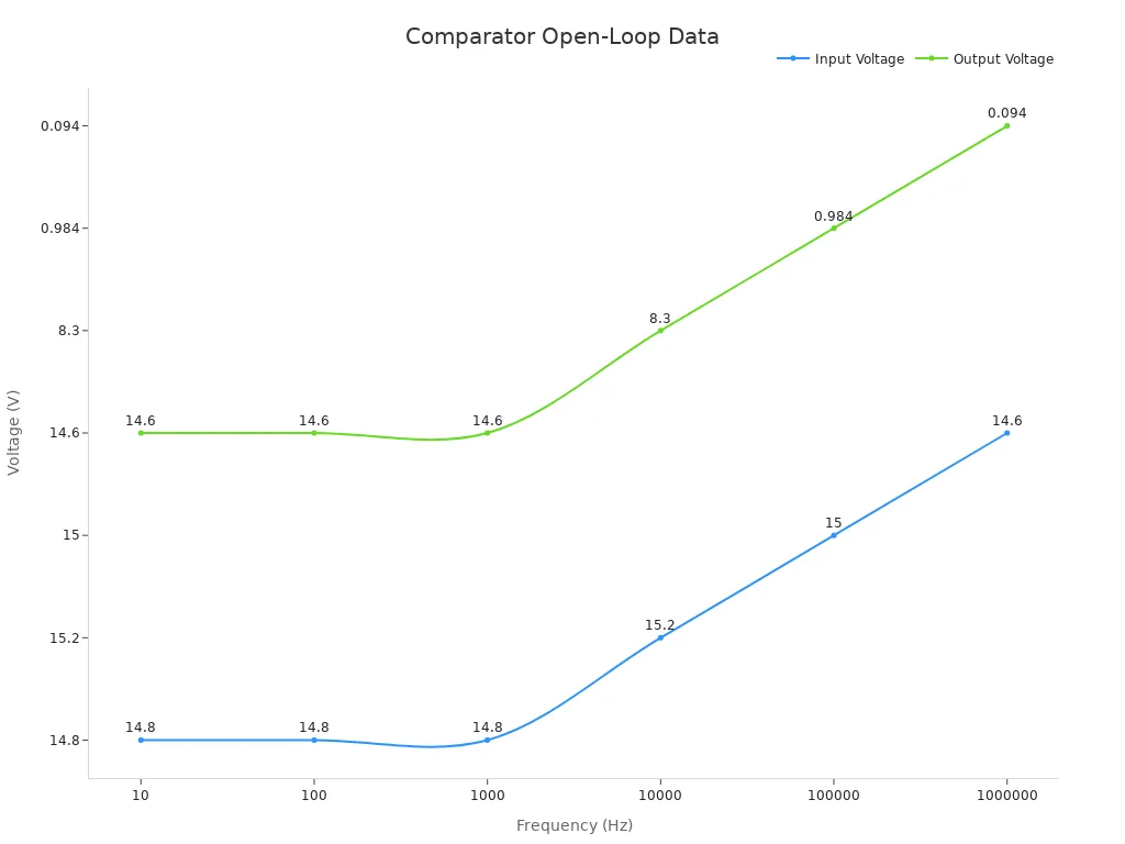
Comparators work in open-loop mode. This means they do not use feedback to control the output. The output only depends on the difference between the input voltages. When you test a comparator, you see the output voltage jumps quickly to high or low as soon as the input crosses the reference. Data shows how the output acts at different frequencies:
Frequency (Hz) | Input Voltage (Vin, V) | Output Voltage (Vout, V) |
|---|---|---|
10 | ~14.8 | ~14.6 |
100 | ~14.8 | ~14.6 |
1,000 | ~14.8 | ~14.6 |
10,000 | ~15.2 | 8.3 |
100,000 | ~15 | 0.984 |
1,000,000 | ~14.6 | 0.094 |
At low frequencies, the output stays close to the supply voltage. When the frequency gets higher, the output drops because the comparator cannot keep up as well. This shows that comparators have high open-loop gain and switch their output quickly without feedback.
Note: Open-loop operation lets voltage comparators make fast choices, but it can also make the output sensitive to noise when the input voltages are very close.
Binary Output
When you use comparators, you get a clear result at the output. This is called a binary output. It only has two states: high or low. You can think of these as "on" and "off." The output changes fast when the input voltage passes a set point. This point is made by the reference voltage at one input.
Comparators do not give a range of values at the output. Instead, you see a quick switch from one state to the other. This makes comparators great for circuits that need fast choices. For example, if you want a buzzer to turn on when a sensor finds high temperature, the comparator sends a high output as soon as the sensor voltage goes above the reference.
Here is how the binary output works in a simple way:
If the voltage at the non-inverting input is higher than the voltage at the inverting input, the output goes high.
If the voltage at the inverting input is higher, the output goes low.
You can see this in many electronic projects. The output from comparators can turn on LEDs, buzzers, or send a signal to a microcontroller. This fast switching helps your circuit react quickly to changes in input voltage.
Tip: Always check the datasheet for your comparator. Some comparators have open-collector outputs, so you may need a pull-up resistor to get a proper high signal.
The table below shows how the output responds to different input voltages:
Non-inverting Input | Inverting Input | Output State |
|---|---|---|
Higher | Lower | High (On) |
Lower | Higher | Low (Off) |
You can use the binary output to make alarms, automatic switches, or digital logic circuits. The clear on/off signal makes it easy to connect comparators to other digital devices.
Comparators work best when you need a fast and sure output. The sharp change in the output helps you avoid confusion in your circuit. You do not have to worry about small changes in the input voltage causing slow or unclear results. The output always gives you a strong and clear signal.
Types of Comparators
Open-Collector
Open-collector comparators are common in simple circuits. They use a transistor at the output. This transistor can only pull the output down to ground. You must add a pull-up resistor to make the output go high. This lets you pick a pull-up voltage that is different from the comparator’s supply. You can also connect several outputs together for a wired-OR setup. This is useful in digital logic.
Here is a table that compares open-collector comparators with other types:
Feature | Open-Collector Comparator | CMOS Comparator | LT1716 Comparator (Class B Pull-up) |
|---|---|---|---|
Output Stage | Transistor pulls output to ground only (open-collector) | Internal push-pull stage drives output high/low | Internal pull-up current source, no external resistor needed |
Pull-up Resistor Requirement | External pull-up resistor required | No external pull-up needed | No external pull-up needed |
Pull-up Voltage Rail Flexibility | Can be pulled up to a different voltage rail than supply | Output tied to supply rails | Can drive loads connected to higher supply rails |
Output Voltage Swing | Limited to pull-up voltage and transistor saturation | Rail-to-rail output swing | Output swings close to supply rails |
Wiring Multiple Outputs | Supports wired-OR connections | Not straightforward | Not specified |
Application Flexibility | Suitable for current-mode applications (e.g., current mirrors) | General purpose, fast switching | Low voltage single supply operation |
You can set up an open-collector comparator as inverting or non-inverting. For an inverting comparator, put your signal on the inverting input. The output goes low if the input voltage gets higher than the reference. For a non-inverting comparator, put your signal on the non-inverting input. The output goes high if the input voltage gets higher than the reference.
Tip: Always use a pull-up resistor with open-collector comparators. If you forget it, the output will not work right.
Push-Pull
Push-pull comparators have two transistors at the output. One transistor pulls the output high. The other pulls it low. You do not need a pull-up resistor for this type. This design gives you a strong and quick output signal. Push-pull comparators are good for circuits that need fast switching.
Tests show push-pull comparators match the input and output very well. They work with both inverting and non-inverting comparator circuits. The output follows the input closely, so you get good results. In tests, push-pull designs handle both rising and falling signals with high accuracy.
Aspect | Push-Pull Comparator | Negative Feedback without Comparator-Adjuster |
|---|---|---|
Dose-Response Alignment | Perfect alignment | Fails to achieve perfect alignment in most cases |
Kinetic Modeling Impact | Performs well in many conditions | Needs special mechanisms for good performance |
Comparator-Adjuster Presence | Included | Lacks this feature |
Mechanistic Insight | Both output states control the load | Feedback alone is not enough |
You can use push-pull comparators for both inverting and non-inverting circuits. This makes them popular in digital electronics.
Single-Supply
Single-supply comparators use just one voltage source. You often find them in battery-powered or simple circuits. These comparators can be set up as inverting or non-inverting. You connect your reference voltage within the supply range. The comparator checks your signal against this reference.
Data shows single-supply comparators respond faster with a stronger input signal. If you lower the supply voltage, the response gets slower. Some single-supply comparators, like the LT1719, keep a steady delay if you add a negative supply. How you connect the output also changes the speed. More load on the output makes the comparator slower.
Parameter | Comparator Example(s) | Key Statistical Insight |
|---|---|---|
Propagation Delay vs. Input Overdrive | LT1719 single 4.5ns comparator | Higher input overdrive reduces propagation delay, showing faster response with increased signal strength. |
Propagation Delay vs. Supply Voltage | LTC6752 single 2.9ns comparator, LT1719 | Lower supply voltage in single-supply systems generally increases propagation delay; LT1719 delay stable if negative supply present. |
Propagation Delay vs. Capacitive Loading | Multiple comparators | Increased capacitive load at output increases propagation delay, varies by manufacturer and device. |
You can use single-supply comparators for both inverting and non-inverting circuits. This makes them useful for many projects, like alarms and sensor circuits.
Dual-Supply
You find dual-supply comparators in more complex circuits. These comparators use two power supplies. One is positive, and one is negative. This setup lets you use a bigger range for signals. You can work with signals below zero volts. Single-supply comparators cannot do this.
With a dual-supply comparator, you connect one supply to +15V. The other supply connects to -15V. This lets the comparator handle both positive and negative voltages. Your circuit design gets more options. Many lab tools and audio devices use dual-supply comparators.
You can make inverting or non-inverting comparator circuits with them. For an inverting comparator, put your signal on the inverting input. Put the reference voltage on the non-inverting input. The output goes low if the signal rises above the reference. For a non-inverting comparator, switch the inputs. The output goes high if the signal rises above the reference. This makes dual-supply comparators helpful for many signal jobs.
Here is a simple table that compares dual-supply and single-supply comparators:
Feature | Dual-Supply Comparator | Single-Supply Comparator |
|---|---|---|
Power Supplies | +V and –V | +V only |
Input Voltage Range | Positive and negative | Positive only |
Output Swing | Full range | Limited by ground |
Common Uses | Lab, audio, sensors | Battery, simple alarms |
Pick a dual-supply comparator if you need to measure signals above and below zero. This is common in audio or AC circuits. You can also use an inverting comparator to find when a signal crosses a set point.
Tip: Always check the datasheet for supply voltage limits. Using the wrong supply can break your comparator.
Dual-supply comparators often switch faster than single-supply types. You get less delay and sharper changes. This helps when your circuit needs quick choices. You can use an inverting comparator to make zero-crossing detectors. These are important in waveform tests.
Try using dual-supply comparators on a breadboard. Build an inverting comparator with a ±9V supply. Use a variable resistor for the reference voltage. Watch the output as your input crosses the reference. This hands-on work helps you learn how dual-supply comparators work.
Comparators vs Op-Amps
Design Differences
Comparators and op-amps are made for different jobs. Comparators are good when you need fast choices in a circuit. They do not have phase compensation inside. This lets them change their output very quickly. Many comparators have open-collector or open-drain outputs. These outputs need a pull-up resistor. This makes it easy to connect to digital logic.
Op-amps are built differently. They have phase compensation capacitance. This part stops unwanted oscillations when using negative feedback. Because of this, op-amps are slower than comparators. Op-amps use a push-pull output stage. This gives a smooth analog output. You use op-amps to make signals bigger or to filter them. They are not just for quick on/off choices.
Tip: Use comparators for fast switching and digital logic. Use op-amps to make signals bigger or to process analog signals.
Functional Differences
Comparators and op-amps do different things in electronics. Comparators compare two voltages and give a clear high or low output. The output can go all the way to the supply rails. This is great for digital circuits. Comparators switch states in nanoseconds. This means your circuit reacts very fast.
Op-amps are best for working with analog signals. They make signals bigger and use feedback to keep the output steady. Op-amps do not switch as fast as comparators. Their output does not always reach the full supply voltage. This makes them not the best for digital logic.
Here is a table that shows the main differences:
Parameter | Comparator Circuits | Operational Amplifier (Op-Amp) Circuits |
|---|---|---|
Output Behavior | Rail-to-rail saturation; output swings fully to V+ or V- rails, suitable for digital logic levels | Near-rail swing; output goes high or low but not necessarily to full supply rails |
Speed | Very fast switching, typically in nanoseconds due to open-loop design | Slower response, typically microseconds, due to internal compensation and closed-loop operation |
Output Structure | Often open-drain or open-collector outputs requiring pull-up resistors; can be push-pull | Push-pull output stage composed of complementary transistors for continuous analog output |
Application Suitability | Ideal for fast digital logic interfacing, voltage level detection, and switching applications | Best suited for linear analog signal processing, amplification, filtering, and low-speed tasks |
Output Compatibility | TTL or CMOS logic compatible outputs; can drive digital logic directly | Outputs not designed to drive digital logic directly; intended for analog loads |
You might think about using op-amps as comparators. Some guides say you can, but there are problems. Op-amps are not made for fast switching. They can give slow or noisy outputs if used as comparators. You may see extra changes near the threshold voltage. Comparators do not have these problems. They are made for quick and clean switching.
Note: Always pick comparators for fast digital choices. Use op-amps for smooth analog jobs like making music louder or filtering signals.
Applications in Electronics
Threshold Detection
Comparators help you find when a voltage passes a set level. This level is called a threshold. When the signal goes above or below this point, the comparator changes its output. Many devices need this feature. For example, a warning light can turn on if a battery gets too low. Comparators make this happen fast and with good accuracy.
Here is a table that explains why comparators are good for threshold detection:
Parameter | Description & Impact |
|---|---|
Working Principle | Comparators check two voltages and switch output fast when input crosses a set voltage. |
Hysteresis | Makes two switching points to stop false changes from noise near the threshold. |
Propagation Delay | Very quick switching (in nanoseconds) helps find changes right away. |
Input Offset Voltage | Small offset voltage (1–3 mV) helps find the exact crossing point. |
Power Consumption | Uses little power (about 110.72 μW at 1 V), so it is good for battery devices. |
Application Examples | Used in voltage checks, battery range detectors, and zero-crossing circuits. |
Specific Models | LM339AN comparator is known for being fast and using little power. |
Design Considerations | Good layout, grounding, and wiring help keep the circuit stable and accurate. |
Comparators give fast and correct switching. They do not use much power, which is good for small gadgets. Hysteresis helps stop wrong switching when there is noise. You see threshold detection in alarms, battery checkers, and automatic switches.
Zero-Crossing
Comparators are also used to find when a signal crosses zero volts. This is called zero-crossing detection. It is important in AC power and sound circuits. The comparator watches the input and changes the output each time the signal goes through zero.
A real example is the Lectrobox zero-crossing detector. It uses a comparator and a voltage divider. Over three days, it counted more than 16 million zero-crossing signals from AC power. The output stayed steady and did not have errors. Tests with a microcontroller and GPS showed it was very accurate, with timing down to about 6 nanoseconds. The system worked even when the signal was messy, with up to 30% distortion. This shows comparators are good for finding zero crossings, even in hard situations.
Zero-crossing detection is used in motor controls, phase-locked loops, and digital timing. Comparators make these jobs possible by giving a quick and clear output every time the signal crosses zero.
Window Detection
Window detection uses comparators to check if a voltage stays between two set points. You pick a high and a low reference voltage. Each comparator checks the input against one of these points. If the signal is between them, the output is high. If the signal goes outside, the output is low.
Window detectors use two comparators to make this voltage window. Each one compares the input to a reference. The outputs work together to show if the signal is inside or outside the window. This way, you can watch voltage ranges very closely. You often see window detection in battery systems and voltage monitors. Comparators work together to give a digital output that is easy to use in other circuits.
You can build window detection circuits for many uses. These circuits help protect devices, watch sensors, and control systems that must stay safe.
Oscillators
You can use comparators to make simple oscillators. Oscillators create signals that repeat over and over. These signals can turn things on and off in a pattern. Square waves are a common type of signal made by oscillators. Many devices need these signals, like clocks, timers, and sound makers. Using a comparator as an oscillator gives you a quick and steady way to make these signals.
To build an oscillator, you need a comparator, a resistor, and a capacitor. The capacitor charges up and then lets out its charge. This makes the voltage at one input go up and down. The comparator checks this voltage against a set level. When the voltage goes past the level, the output changes from high to low or low to high. This keeps happening, so you get a square wave that repeats.
Here is how you can make a simple comparator oscillator:
Put a resistor and a capacitor in a line.
Connect one end of the resistor to the comparator’s non-inverting input.
Attach the other end of the capacitor to ground.
Use a reference voltage at the inverting input to set the level.
The output will change each time the capacitor voltage goes past the level.
Tip: You can change how fast the oscillator works by picking different resistor or capacitor values. A bigger resistor or capacitor will make the signal slower. A smaller resistor or capacitor will make it faster.
Oscillators with comparators are helpful in many projects. You can use them to blink LEDs, make buzzers sound, or give timing signals to digital circuits. These circuits are simple and do not need many parts.
Here is a table that shows what comparator oscillators can do:
Application | Purpose |
|---|---|
LED Flasher | Makes lights blink |
Tone Generator | Produces sound signals |
Clock Pulse Source | Times digital electronics |
PWM Controller | Controls motor speed or light |
You can add hysteresis to the circuit. Hysteresis helps the output switch cleanly, even if there is noise. This keeps your signal steady and strong.
If you want to try this, use a breadboard and some basic parts. Watch how the output changes when you use different resistor or capacitor values. You will see how easy it is to make repeating signals for your projects.
Oscillators are a very useful way to use comparators. They show how simple circuits can make timing and control jobs in electronics.
Practical Tips for Beginners
Reading Datasheets
When you use comparators, always read the datasheet first. The datasheet explains how the device works and what it can handle. It also shows the limits of the device. You should check the datasheet before you build your circuit. Here are some easy steps to follow:
Check the absolute maximum ratings. This keeps the device from breaking.
Look at the conditions for each number, like temperature or voltage. The numbers only work under these conditions.
Notice the difference between typical and minimum or maximum values. Typical values are common, but only the minimum or maximum are guaranteed.
Check the mechanical details, pinouts, and block diagrams. These help you connect the comparator the right way.
Read the small notes and application tips. These parts give extra help for using the device safely.
If you see a value that changes a lot, you might need to test your circuit or ask for help.
Tip: Always read the datasheet and manual all the way through. This helps you avoid mistakes and keeps your projects safe.
Simple Circuits
You can learn by making simple circuits with comparators. A basic op-amp comparator is a good project for beginners. You only need a few parts: an op-amp, some resistors, a breadboard, wires, and a power supply. In this project, you connect two voltages to the op-amp. The comparator checks which voltage is higher and gives a digital output.
Try a light detector. Use a photoresistor for one input and a set voltage for the other. The output can turn on an LED when it gets dark.
Make a simple overvoltage protection circuit. The comparator watches the voltage. If it gets too high, the output can turn off the power to protect your devices.
These projects show how comparators work in real life. You also learn how to protect your circuits from damage.
Troubleshooting
Sometimes, your comparator circuit does not work right. Here are some common problems and how to fix them:
If you use a comparator like the LM339, remember it has an open-collector output. You need a pull-up resistor, or the output will not go high.
Make sure your input voltages stay inside the power supply range. If the voltage goes below -0.3V, you can break the comparator.
For AC signals, add a DC offset to keep the input safe.
If your circuit switches too fast near the threshold, add hysteresis. This helps stop quick changes.
Check your wiring. Small mistakes or a bad chip can cause trouble.
Use a steady voltage reference. If the reference moves, your comparator may act strange.
If you see double triggers or noise, try adding positive feedback or a small capacitor to make it stable.
Note: Always check your circuit before turning on the power. This helps stop damage and keeps your overvoltage protection working.
A quick troubleshooting table:
Problem | Possible Cause | Solution |
|---|---|---|
Output always low | No pull-up resistor | Add pull-up resistor |
Output unstable near threshold | No hysteresis | Add hysteresis resistor |
Device gets hot or fails | Input voltage too high/low | Check input range and supply |
Output does not switch | Bad wiring or faulty chip | Recheck connections and parts |
By following these tips, you can build safe and strong circuits with comparators.
Now you understand how comparators help circuits decide fast. These devices are important in digital electronics and control systems. Try making easy circuits, like a voltage detector or an LED flasher, to see them in action. You can use LTspice simulation software to add things like hysteresis and make your designs better. There are many worksheets, textbooks, and video lessons that help you learn more about comparators and how they are used in real life.
FAQ
What is the main job of a comparator?
A comparator checks two voltages and tells you which one is higher. The output is either high or low. You use this to make quick decisions in your circuits.
Can you use an op-amp as a comparator?
You can use an op-amp as a comparator, but it does not work as well. Op-amps switch slower and may not give a clean output. Always choose a real comparator for best results.
Why does my comparator output stay low?
Your output may stay low if you forget the pull-up resistor on an open-collector comparator. Check your wiring and make sure the input voltages are correct. Also, look for a faulty chip.
What does hysteresis do in a comparator circuit?
Hysteresis adds two switching points. This stops the output from changing too quickly when the input voltage is close to the reference. You get a more stable output, even with noise.
How do you connect a comparator to an LED?
Connect the comparator output to the LED through a resistor. If you use an open-collector output, add a pull-up resistor. The LED lights up when the output goes high.
What is the difference between inverting and non-inverting comparators?
In an inverting comparator, the signal goes to the inverting input. The output goes low when the signal passes the reference. In a non-inverting comparator, the signal goes to the non-inverting input. The output goes high when the signal passes the reference.
Can comparators work with AC signals?
Yes, comparators can work with AC signals. You may need to add a DC offset to keep the input within safe limits. Comparators can detect zero crossings or signal peaks in AC circuits.
Do comparators need a power supply?
Yes, comparators need a power supply to work. You must connect them to the correct voltage, as shown in the datasheet. Using the wrong supply can damage the device.
See Also
A Beginner’s Guide To Oscilloscopes And Multimeters
Fundamental Concepts Of Counters In Digital Electronics
Key Differences Among Commonly Used Inverter Chips Explained
Simple Explanation Of Inverting Versus Non-Inverting Amplifiers
The Importance Of Optocoupler Symbols In Electronic Circuits
