Understanding Zero-Cross Detectors in Electronics
Understanding zero-cross detectors helps engineers work with ac signals more accurately. A zero crossing happens when an ac wave changes from positive to negative or the other way. Zero-crossing means the signal goes through the zero-voltage line. Detecting zero-crossing lets circuits have exact timing and control. Think of a race where a runner crosses the starting line—zero crossing is like that line for electrical signals. Zero-cross detectors can measure phase shift error as small as 0.0314 radians at 50 Hz. They can also find zero-crossing in signals with up to 30% distortion, but not at 40%. Finding zero-crossing points helps keep power use safe and efficient.
Metric | Value | Description |
|---|---|---|
Phase shift error | 0.0314 rad | Measured phase shift error at 50 Hz using Arduino Uno microcontroller |
Total Harmonic Distortion (THD) detection limit | Up to 30% | Zero-cross points detected reliably in distorted signals with THD up to 30% |
THD detection failure | 40% | System fails to detect zero-cross points at 40% THD |
Key Takeaways
Zero-cross detectors find when an AC signal goes through zero volts. They change smooth waves into sharp digital pulses. They help control timing in circuits. They make circuits safer. They lower electrical noise by switching at zero voltage. There are two main types. Inverting detectors flip the signal phase. Non-inverting detectors keep the output in phase with the input. Zero-cross detectors are used in power control and synchronization. They are also used for motor speed, light dimming, and solid-state relays. These detectors make systems more reliable. They help relays last longer. They save energy by lowering voltage spikes and interference. They work best with clean signals. They can handle up to 30% distortion. They may not work well with more noise or distortion. Picking the right circuit parts helps. Adding filters or hysteresis lowers false triggers and makes them more accurate. Zero-cross detectors give fast and simple timing solutions. They are easier than other methods that need a lot of computing.
What Are Zero-Cross Detectors?
Definition
Zero-cross detectors are special circuits that find when a signal crosses zero volts. These circuits help spot the exact time a signal changes from positive to negative or the other way. These times are called zero-crossing points. The detector works with analog signals and sorts each crossing by which way the sign changes. Engineers use zero-cross detectors to track these points in signals. This helps them measure changes, like strain in materials, or control timing in devices. This method is fast and works well in real-time systems, especially when signals change a little.
Note: Knowing about zero-cross detectors helps engineers make circuits that react fast and correctly to changes in signals.
Empirical Data Highlights
Zero-cross detectors change sine waves into square waves. This makes timing and phase easier to measure.
Their outputs go to universal counters. These counters check the period of a signal and show the detector works.
Engineers use reciprocal counting to make measurements more accurate.
Devices like the HP 5315A counter and microcontrollers with timers show how zero-cross detectors work in real life.
Core Function
The main job of a zero-cross detector is to mark the time a signal crosses zero volts. This turns a smooth signal into a sharp digital pulse. The output can control other parts of a circuit or help measure time and frequency. In real use, the output often looks like a square wave. Digital systems can read this easily.
Performance Aspect | Benchmark / Description |
|---|---|
Glitch-free operation | Tens of millions of samples collected without a single glitch |
Input filtering | Low-pass RC filter with cutoff near mains frequency (50/60 Hz) |
Output phase shift | Approximately 500 microseconds due to RC filter |
Output response time | Under 100 nanoseconds achievable by removing filter capacitor |
Comparator used | MCP6561 with built-in hysteresis |
Timestamp resolution | About 6 nanoseconds using STM32G431 microcontroller timestamper |
Frequency accuracy of clock | Better than 1E-10 over 1 second using GPS-disciplined oscillator |
Frequency measurement stability | Phase errors on the order of 1E-5 over several days, comparable to quartz crystal oscillators |
Application focus | Precise mains frequency monitoring and time error correction experiments |
This table shows zero-cross detectors can work for a long time without mistakes. They answer quickly and can measure time very well. These features make them useful for checking power line frequency and fixing timing errors.
Zero-Crossing in AC Signals
Zero crossing happens when a signal, like a sine wave, moves from positive to negative voltage or back. In real circuits, engineers use devices like op-amps to find these times. For example, a circuit might use a transformer to lower the AC voltage. Then it sends the signal to an op-amp. The op-amp checks the signal against zero volts. When the signal crosses zero, the op-amp output jumps fast and makes a square wave. This square wave marks each zero crossing.
Tests show that every time the AC wave crosses zero, the detector makes a pulse. A sine wave crosses zero two times in each cycle, so the detector makes two pulses per cycle. Devices like pinball machines use these pulses to control lights and motors. The zero crossing signal acts like a clock and helps the device stay in sync with AC power.
Understanding zero-cross detectors means knowing how they turn smooth signals into clear, timed pulses. This is important for many electronics projects, like measuring frequency or controlling power safely.
Operation
Detection Principle
Zero-cross detectors find the exact time a signal crosses zero volts. This is called zero-crossing detection. The detector checks the input signal against a reference voltage set at zero. When the signal changes from positive to negative or the other way, the detector changes its output. This makes a sharp digital pulse for each zero crossing.
How well zero-crossing circuits work depends on their parts. The table below shows how different comparators and devices work for zero-crossing detection:
Circuit Type | Comparator/Device Used | Pulse Width | Propagation Delay | Notes |
|---|---|---|---|---|
Basic transistor zero crossing | Transistor Q1 | ~600µs (0.6ms) | N/A | Simple, broad pulse; suitable for low frequency (50/60Hz); pulse width is ~5% of period. |
XOR gate edge detector | 74HC86 XOR gate | ~50ns | ~11ns | High speed; pulse width controlled by R1 and C1; suitable up to 100kHz or above. |
LM393 comparator detector | LM393 comparator | ~70µs | N/A | High performance; pulse width adjustable by resistor; tested and reliable for zero-cross. |
LM358 op-amp test detector | LM358 op-amp | ~250µs | N/A | Slower than LM393 but still centered on zero crossing; used for comparison. |
AMC23C12 isolated window comp. | AMC23C12 IC | <1µs | <1µs | Specialized IC; very fast response; suitable for isolated mains zero-cross detection. |
This table shows that some circuits react fast, while others make wider pulses. Engineers pick the right circuit based on how quick and accurate they need it to be.
Circuit Components
Op-Amps and Comparators
Op-amps and comparators are the main parts of most zero-cross detectors. An op-amp can work as a voltage comparator. It checks if the input is above or below the reference voltage. When the input crosses zero, the op-amp output jumps quickly between high and low. Comparators like the LM393 or special ICs such as the AMC23C12 switch fast and work well at each zero crossing.
Other important parts are:
Clamp diodes: These keep the op-amp safe from voltage spikes.
Positive feedback (hysteresis): This helps the output switch cleanly and stops false triggers from noise.
Filtering capacitor: A small capacitor, like 0.1 µF, removes high-frequency noise from the output.
Reference Voltage and Signal Path
The reference voltage is usually set to zero volts in a zero-cross detector. This lets the circuit find the exact spot where the input crosses zero. The input signal goes through a path with resistors, diodes, and sometimes a bridge rectifier. The bridge rectifier makes sure the pulses always have the same direction, so detection is steady.
Key things for good zero-crossing detection include:
Component/Specification | Details and Purpose |
|---|---|
Operational Amplifier (Op-Amp) | Used as a comparator; compares input signal with 0V reference to detect zero crossing points. |
Reference Voltage | Set to zero volts (0V) to detect the exact zero crossing of the AC input signal. |
Positive Feedback (Hysteresis) | Added to reduce noise and false triggering by making output switch faster and more stable. |
Power Supply Voltage | Typically 5V DC to power the output circuit and ensure compatibility with microcontroller logic. |
Filtering Capacitor | Small capacitor (e.g., 0.1 µF) placed between output and ground to filter high-frequency noise. |
Optocoupler | Provides isolation between high-voltage AC input and low-voltage output for safety and signal integrity. |
Bridge Rectifier | Used in optocoupler-based detectors to ensure pulses have the same polarity for consistent detection. |
Clamp Diodes | Protect the operational amplifier from voltage spikes on the input signal. |
Output Voltage Levels | Must be compatible with microcontroller logic levels (TTL 5V or level-shifted for 3.3V MCUs). |
Safety and Insulation | Proper insulation and isolation are critical to safely handle AC input and protect circuitry. |
Tip: Always use good insulation and safety steps when connecting AC input. Use voltage dividers or level shifters for microcontrollers that use 3.3V logic.
Step-by-Step Process
Zero-cross detectors follow these steps to find each zero crossing:
The circuit uses an op-amp or comparator as an inverting or non-inverting comparator. The reference voltage is set at zero.
In an inverting detector, the input connects to the inverting terminal. The non-inverting terminal connects to ground.
When the input is positive, the op-amp output goes low. When the input is negative, the output goes high. This flips the input wave.
The output changes state at each zero crossing, making a square wave.
Protection diodes stop high voltages from hurting the op-amp.
In a non-inverting detector, the input connects to the non-inverting terminal. The inverting terminal connects to ground.
Here, the output goes high when the input is positive and low when the input is negative. The output square wave matches the input.
The output wave shows clear switching at each zero crossing, going between high and low.
This makes sure the detector marks every zero crossing with a sharp, steady pulse.
This way, circuits can react fast and correctly to zero crossings. The output pulses can control other devices or help measure the input signal’s frequency. Engineers use this process for safe and efficient work in many electronic systems.
Types

Inverting
An inverting zero-cross detector uses an op-amp or comparator. The input signal goes to the inverting (−) terminal. The non-inverting (+) terminal connects to a reference voltage. This voltage is usually set at zero volts. When the input signal is above zero, the output goes low. If the input drops below zero, the output jumps high. This makes a square wave that is flipped from the input. The output changes phase by 180 degrees. Engineers call this phase inversion.
Inverting zero-cross detectors are used when the output must be opposite of the input. Some timing circuits need this flipped signal to start other actions. The inverted output can also help lower noise in some designs.
Tip: Inverting detectors are good for systems that need a clear, opposite-phase signal for control or measurement.
Non-Inverting
A non-inverting zero-cross detector works in a different way. The input signal connects to the non-inverting (+) terminal. The inverting (−) terminal connects to the reference voltage, set at zero volts. When the input is above zero, the output goes high. When the input is below zero, the output goes low. The output matches the input’s direction. There is no phase inversion.
Non-inverting detectors are helpful when the output should follow the input. Many digital circuits and microcontrollers use this type. It makes the logic easier to understand. The output changes at the same time as the input crosses zero. This keeps timing simple.
Note: Non-inverting detectors are common in systems that need direct, easy-to-read signals for more work.
Differences
The main difference is how the output matches the input. Inverting detectors flip the output’s phase. Non-inverting detectors keep the output in phase with the input. The choice depends on what the circuit needs.
The table below shows how each type works:
Detector Type | Input Terminal | Reference Terminal | Output Voltage Polarity for Positive Input | Output Voltage Polarity for Negative Input | Output Waveform Characteristic |
|---|---|---|---|---|---|
Inverting (−) terminal | Non-inverting (+) terminal (0V) | Output saturates negative (−V_sat) | Output saturates positive (+V_sat) | Output waveform is inverted relative to input polarity (phase inversion) | |
Non-inverting Zero Crossing | Non-inverting (+) terminal | Inverting (−) terminal (0V) | Output saturates positive (+V_sat) | Output saturates negative (−V_sat) | Output waveform matches input polarity (no phase inversion) |
Inverting detectors make an output that is the opposite of the input’s direction.
Non-inverting detectors make an output that matches the input’s direction.
Engineers pick the type based on what the system needs. Some systems need phase inversion to work right. Others need the output to match the input for simple logic. Both types are important in electronics.
Waveforms and Zero-Crossing Points

Input Signal Behavior
AC signals from things like power lines make a smooth sine wave. The zero-crossing happens when the signal goes from positive to negative or back. These times are called zero-crossing points. On a graph, the sine wave crosses the zero line again and again. For example, in one cycle, it crosses zero at 0°, 180°, and 360°. At these points, the voltage changes direction fast. The slope of the wave is steepest here. This happens because of how electromagnetic induction works in generators. The input signal always passes through these zero-crossing points. This makes them easy to see on an oscilloscope.
The zero-crossing is not just a random thing. It shows the exact time when the signal changes direction. This is important for measuring phase and frequency.
Output Signal
Zero-cross detectors watch for every zero crossing in the input. When the signal crosses zero, the detector makes a sharp digital pulse. This output looks like a square wave. It switches quickly between high and low. The square wave helps digital circuits read timing better. Each pulse matches a zero-crossing point in the original signal. Engineers use these pulses to control devices or measure time. For example, measuring the delay between zero-crossing points of two signals shows a phase shift. If one signal crosses zero 0.1 milliseconds after another in a 1 millisecond cycle, this means a phase shift of about −36°. The output from the zero-cross detector gives a clear way to track these changes.
Timing at Zero-Crossing Points
Good timing at zero-crossing points is very important in electronics. Circuits need to know the exact moment the signal crosses zero. This helps control switching, measure frequency, or keep devices in sync. Zero-crossing detection must be accurate, but real things can affect timing. Transformer wiring, core magnetization, and noise in the AC line can cause small shifts in the zero crossing. Some circuits use hysteresis to cut noise, but this can make the zero-crossing area wider. Advanced algorithms can help timing by focusing more on the zero-crossing area. This gives better accuracy without slowing the system. Engineers use zero-crossing detection to keep systems safe and efficient, especially in power control and phase measurement.
Accurate zero-crossing timing helps stop errors, lowers wear on parts, and makes sure devices work well together.
Applications of Zero Crossing
AC Power Control
Zero-crossing detectors are important for AC power control. They help switches like solid-state relays and triacs turn on or off at the right time. This time is when the AC voltage crosses zero. Switching at zero-crossing lowers electrical noise and stress. It also protects sensitive equipment and makes switches last longer. When a device switches at zero, it avoids sudden voltage jumps. This keeps the power flow smooth and safe.
Many home appliances use zero-crossing detection for heaters, fans, and other loads. The detector sends a signal to the control circuit. The control circuit then turns the switch on or off at the best time. This helps stop sparks and power surges. Engineers pick zero-crossing control for systems that need to be safe and reliable.
Synchronization
Zero-crossing detection is needed for synchronization in power systems. It helps different parts of a system work together. The detector marks the exact time the AC wave crosses zero. This lets devices match their actions with the power line.
Modern electronics use zero-crossing points to check if electrical waves are steady. For example, power swings in a grid can be tracked by watching zero-crossing points. Engineers use these points to find times when the system is not stable. They also use them to spot out-of-step problems in generators. By looking at these points, they can see if a generator is working with the grid or not.
Zero-crossing detectors make protection systems more reliable and safe. They let systems stay off during normal times and only act when needed. This stops false alarms and keeps the power network steady. The detectors also help set limits, like keeping the load angle below 20.5°, to see if the system is stable.
Zero-crossing detection gives engineers a simple way to check if devices work together or if there is a problem.
Key synchronization benchmarks influenced by zero-crossing detectors:
Instability time and frequency rate of power swings are found using zero-crossing points.
Out-of-step problems in generators are easier to detect.
Stability of electrical waves is checked with load angle limits.
It helps tell the difference between synchronous and asynchronous operations.
Protection systems become more reliable and safe.
Zero-crossing points show when synchronization is lost during unstable swings.
Protection systems stay off during stable swings, stopping false alarms.
Motor and Light Dimming
Zero-crossing detectors also help control light brightness and motor speed. They work with dimmers and speed controllers to switch power at zero-crossing. This cuts down on flicker and noise in lights and motors.
But there are limits to how well zero-crossing detection can dim lights. Solid-state relays with zero-crossing detection only switch at zero. This means the shortest time the power can be on is half an AC cycle. Because of this, smooth dimming or fine speed control is hard. People may see flicker or hear buzzing when trying to dim lights or control motors very precisely.
Basic dimming can be done with an Arduino and a triac using zero-crossing pulses. Still, the dimming is not very smooth. The system cannot dim below about 5% power without better timing. Using pulse-width modulation signals with solid-state relays and zero-crossing circuits does not give smooth dimming. The relay only switches at zero, not during the AC half cycle.
Zero-crossing detection works well for simple on/off control and basic dimming.
Fine dimming or exact speed control needs more advanced methods.
Staying in sync with the AC wave is needed to stop phase drift and interference.
For most homes and simple devices, zero-crossing detection gives safe and basic dimming. For advanced lighting or motor control, engineers use more complex timing circuits.
Solid-State Relays
Solid-state relays, or SSRs, are important in today’s electronics. These relays use electronic parts, not moving ones, to switch power. SSRs often control things like heaters, motors, and lights. Many engineers pick SSRs because they last longer and switch faster than old-style relays.
Zero-cross detectors help SSRs work even better. With zero-cross switching, the SSR turns on or off only when the AC voltage is at zero. This timing cuts down on electrical noise and keeps equipment safe. The relay does not make sudden voltage jumps. This means there are fewer sparks or chances for damage. So, the system works more smoothly and safely.
Zero-cross switching in SSRs lowers stress on the relay and the load. This means fewer problems and less time fixing things.
Companies make SSRs with zero-cross features to make them more reliable. For example, Littelfuse SSRs with zero-cross switching help stop problems in AC heating systems. These relays need less fixing and last longer. People do not have to change parts as often, and the system is easier to take care of. The system keeps working for longer, so there is less time spent on repairs.
The table below lists some main benefits of SSRs with zero-cross detectors:
Feature | Benefit |
|---|---|
No moving parts | Lasts longer |
Zero-cross switching | Makes less electrical noise |
Fast response | Protects sensitive devices better |
Reduced maintenance | Fewer parts to replace |
Improved uptime | Less time when the system is down |
Engineers use SSRs with zero-cross detection where reliability is very important. Hospitals, factories, and data centers all need equipment that works all the time. SSRs with zero-cross detectors help by giving steady and dependable performance.
Some SSRs also have extra safety parts. For example, optocouplers keep the control side and the load side separate. This keeps both people and control electronics safe from high voltages.
SSRs with zero-cross detectors are great for:
Industrial automation
HVAC systems
Lighting control
Power supplies
Advantages and Limitations
Benefits
Zero-cross detectors give many helpful benefits in electronics. These circuits let engineers know the exact time a signal crosses zero volts. This skill is useful in lots of real-world jobs.
Zero-cross detectors block out background noise but keep the main parts of a signal. This helps them spot quick changes, like in underwater sound checks or power line tests.
They work faster and need less computer power than harder methods, like wavelet-based detectors. This makes them good for systems that must act right away.
When used with energy detection, zero-cross detectors can find short, sudden signals fast and correctly. This is important in jobs like navy monitoring, where quick action is needed.
These detectors help find and sort different kinds of signals, like natural sounds or sounds made by people.
Tests and studies show zero-crossing detection lowers noise, keeps key signal details, and is easy to use.
Zero-cross detectors help engineers make systems that act fast and work well, even when there is a lot of noise.
Safety and Efficiency
Zero-cross detectors make electronic systems safer and save more energy. They switch at the zero voltage point of the AC wave. This timing cuts down on electrical noise and stops sudden strong currents that can hurt equipment.
By switching at zero-crossing, these circuits lower electromagnetic interference. This keeps systems steady and saves energy.
This way also helps relays and contacts last longer. Less arcing and fewer voltage spikes mean less damage, so you do not need to fix or replace parts as often.
Devices that use zero-crossing control, like smart lights, avoid false triggers and stop too much light. This saves extra energy and cuts down on light pollution.
Some products, like the LongJoin JL207C photocontrol, use zero-cross switching to lower stress on parts and keep standby power low.
Feature | Safety/Efficiency Benefit |
|---|---|
Zero-crossing switching | Reduces noise and inrush current |
Lower EMI | Improves system stability |
Extended relay life | Cuts maintenance and replacement costs |
Accurate dimming | Saves energy and reduces light pollution |
These features make zero-cross detectors a smart pick for systems that need to save energy and work well.
Challenges
Zero-cross detectors also have some problems. They may not work well if signals have lots of distortion or noise. For example, if the signal has over 30% total harmonic distortion, the detector might miss some zero-crossing points.
Some circuits need extra parts, like filters or optocouplers, to safely handle high-voltage AC.
Noise, transformer wiring, or magnetization can change timing and cause small mistakes.
In light and motor control, zero-crossing detection can make it hard to dim lights or change speed smoothly. The system may not let you make very small changes.
Harder jobs may need more advanced timing circuits or software to get the best results.
Engineers must balance the simple and fast work of zero-cross detectors with the need for accuracy and flexibility in tough situations.
Comparisons
Zero-Cross Detectors vs Comparators
Zero-cross detectors and comparators both help with signal processing. A comparator checks if one voltage is higher than another. It changes its output when the input passes a set reference voltage. Zero-cross detectors use comparators but focus on when a signal crosses zero volts. This makes them good for timing and keeping things in sync.
Zero-cross detectors often have extra parts like hysteresis or filters. These parts help stop noise and false signals. Comparators by themselves might react to tiny voltage changes. This can make their outputs jump around in noisy places. Zero-cross detectors give a cleaner and steadier digital pulse at each zero crossing.
A study looked at different ways to detect zero crossings. It compared single-threshold and double-threshold detectors. Double-threshold detectors, which are like advanced comparators, were more accurate and steady than single-threshold ones. The table below shows how each method works at different signal-to-noise ratios (SNR):
Method | SNR (dB) | Bias (lower is better) | Std Dev (lower is better) | Remark |
|---|---|---|---|---|
Improved method | 2 | -39 | 26 | Best |
4 | -22 | 25 | ||
6 | -12 | 22 | ||
8 | -3 | 17 | ||
Double-threshold | 2 | 41 | 68 | Good |
4 | 21 | 69 | ||
6 | 12 | 47 | ||
8 | 0 | 53 | ||
Single-threshold | 2 | 55 | 154 | Worse |
4 | 67 | 147 | ||
6 | 62 | 135 | ||
8 | 72 | 139 |
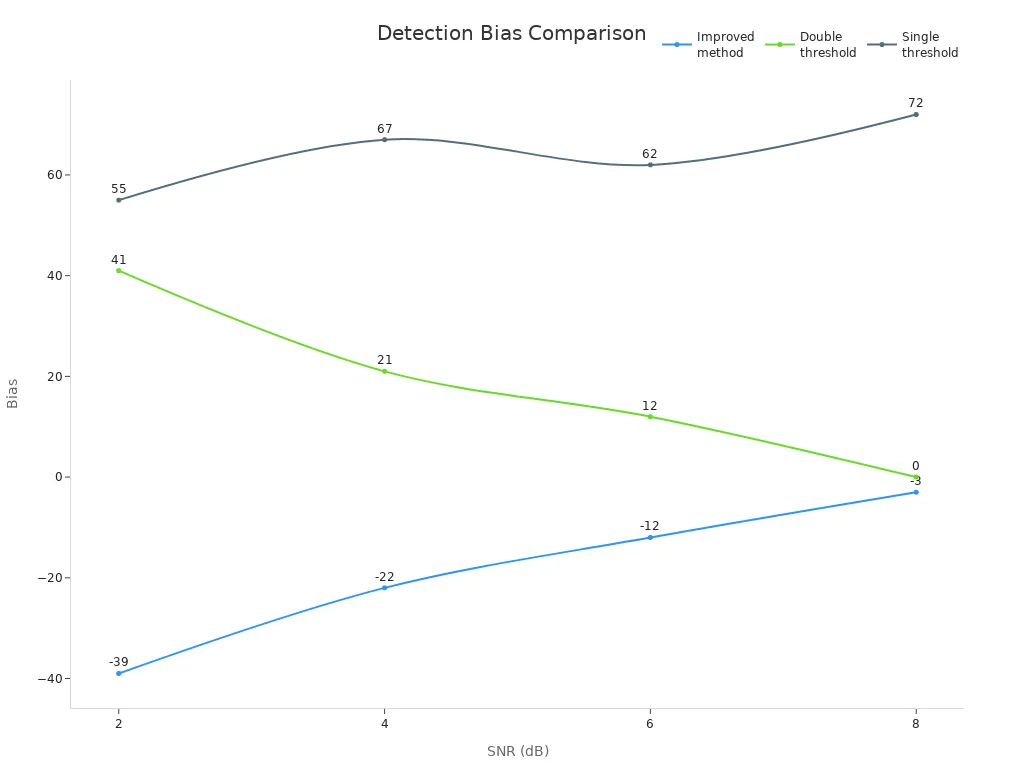
Double-threshold detectors find zero crossings better and let you balance between missing signals and false alarms. This makes them a better pick for jobs that need exact timing and fewer mistakes.
Zero-Cross Detectors vs Schmitt Triggers
Schmitt triggers and zero-cross detectors both turn analog signals into digital pulses. But they are used for different things. A Schmitt trigger has two threshold voltages. It only switches its output when the input goes above the top threshold or below the bottom one. This makes Schmitt triggers strong against noise and gives clean switching, even with slow or messy signals.
Zero-cross detectors only react when the input crosses zero volts. They do not use two thresholds. This makes them more sensitive to small changes near zero. This is important for timing in AC power control and phase checks.
Some new ways to detect signals, like wavelet transforms and fuzzy logic, do even more. Wavelet transforms look at signals in many ways and can handle tricky patterns. Fuzzy logic can deal with mixed-up data and copy how people make choices. But these methods need more computer power and may not work well for real-time control.
Zero-cross detectors: Best for exact timing and keeping things in sync.
Schmitt triggers: Best for blocking noise and giving steady digital outputs.
Advanced methods: Best for hard signal checks but need more computer power.
Engineers pick these circuits based on what their project needs. For quick and simple zero detection, zero-cross detectors are best. For noisy or slow signals, Schmitt triggers work better. Advanced methods are good for research or special jobs where finding patterns and being exact is most important.
Zero-cross detectors let engineers know when an AC signal hits zero volts. These circuits are important for safe and smart power control. They help with timing in lots of electronic devices. People who like electronics can make easy zero-cross detectors at home to learn.
If you want to learn more, you can read about phase measurement, Schmitt triggers, or advanced signal processing. Books about electronics or online videos can show you how to do projects with your own hands.
FAQ
What is a zero-cross detector used for?
A zero-cross detector helps a circuit know when an AC signal crosses zero volts. Engineers use this for timing, switching, and checking frequency in many devices.
Can zero-cross detectors work with any AC signal?
Zero-cross detectors work best with clean sine waves. They may have trouble if the signal is very noisy or distorted. Most can handle up to 30% distortion before missing crossings.
Why do engineers use zero-cross switching in relays?
Zero-cross switching lowers electrical noise and stress on relays. This helps protect equipment and makes relays and loads last longer.
How does a zero-cross detector improve safety?
Zero-cross detectors let circuits switch at the safest time in the AC cycle. This cuts down on sparks, voltage spikes, and damage to sensitive electronics.
What is the difference between inverting and non-inverting zero-cross detectors?
An inverting detector flips the output’s phase. A non-inverting detector keeps the output in phase with the input. Engineers pick the type their circuit needs.
Can someone build a zero-cross detector at home?
Yes! Many hobbyists make simple zero-cross detectors with op-amps or comparators. These basic circuits use only a few parts and can connect to microcontrollers for projects.
Do zero-cross detectors work with microcontrollers?
Zero-cross detectors often connect to microcontrollers. The detector sends a digital pulse at each zero crossing. Microcontrollers use these pulses for timing, measuring, or control.
What are common problems with zero-cross detectors?
Noise, signal distortion, or bad circuit design can cause missed or false zero crossings. Using filters, good shielding, and careful layout helps make them more accurate.
See Also
An Introduction To Counters Used In Digital Electronics
A Beginner’s Guide To Oscilloscopes And Multimeters
Simple Explanation Of Inverting Versus Non-Inverting Amplifiers
