Hands-On Tutorial for Laser Diode Integration with Arduino
You can learn to connect and program a laser diode with Arduino in this tutorial. A laser diode makes a narrow beam of light. This is helpful for finding objects or lining things up in electronics projects. The steps in this tutorial are simple, so beginners can do them. Safety is very important. Studies show that low-power lasers used carefully can help healing. No bad effects have been reported.
| Laser Parameters | Wavelength: 915 nm | Power: 0.5 W | No bad effects reported in careful use |
Key Takeaways
Laser diodes make a narrow light beam. They need careful use. You must control the current to stop damage.
Use a current-limiting resistor or a driver circuit. This keeps your laser diode safe from too much current.
Always follow safety rules. Never point lasers at people or shiny things. Wear the right laser safety glasses.
Connect the laser diode module to Arduino pins the right way. VCC goes to 5V. GND goes to ground. Signal goes to a digital output pin.
Write easy Arduino code to turn the laser on and off. Use comments to make your code clear and simple to fix.
Test your circuit with care before turning it on. Double-check your wires. Use tools like a multimeter to find problems.
Start with easy projects like a laser tripwire. Then try harder ideas with more laser modules and temperature control.
Keep your workspace safe. Use warning signs, eye protection, and set up your area right. This helps stop accidents and keeps your equipment safe.
Laser Diode Basics
What Is a Laser Diode?
A laser diode is a special kind of light source. It uses a small piece of semiconductor to make a strong, focused light beam. You can think of it like a high-tech LED. When electricity goes through the diode, electrons and holes meet in the active layer. This makes energy come out as photons. The photons bounce between mirrors inside the diode. This creates a narrow and powerful laser beam.
Laser diodes work by making electrons give off light in semiconductors.
The main parts are a p-n junction, special layers called heterostructures, and a resonator that helps the light grow.
Laser diodes are small, use little power, and can turn on and off fast.
Some types are DBR, DFB, and VCSELs, and each has its own job.
Laser diodes need to be handled with care. They use about 3V and usually need 20mA. You should use a resistor to keep the current safe. If you connect them the wrong way, they will not work.
Component/Aspect | Specification/Description |
|---|---|
Laser Diode | 1.5W power, 445nm wavelength (blue light), 12mm housing with focusable lens |
Cooling | Needs a heatsink for safe operation |
Current Regulation | Use a voltage regulator or resistor to control current |
Power Supply | Minimum 10V DC supply required |
Common Arduino Uses
You can use a laser diode with an arduino for many fun projects. Here are some ideas:
Make a laser tripwire to spot movement.
Build a distance sensor using a light-dependent resistor.
Control a laser pointer for a robot or a moving system.
Make a simple way to send messages using laser flashes.
For example, some students used an arduino to control a laser diode from an old DVD player. They made a small heater by pointing the laser at something and checking the temperature with a sensor. In another project, an arduino moved a laser beam back and forth to help a robot find weeds in a garden. These examples show that laser diodes can do many things in arduino projects.
Safety Tips
⚠️ Always be careful when using laser diodes. Even weak lasers can hurt you if you are not careful.
Never point a laser at people or animals.
Do not shine the laser at mirrors or shiny things.
Never look straight into the laser beam.
Use the lowest power you need for your project.
Keep laser diodes away from small children.
Take out batteries or unplug the laser when not using it.
Learn about blue light risks, which can harm your eyes.
Many accidents happen when people do not follow these rules. For example, a pilot in England was blinded by a laser pointer while landing. Governments have made strict rules about laser pointers to keep people safe. Learning and following safety rules is the best way to stop accidents, so always read instructions and be careful.
Components and Tools
Laser Diode Module
You need a laser diode module to begin your project. This small part makes a narrow light beam. Most laser modules for arduino are easy to connect. They usually have a lens and simple pins. The table below shows what a common module has:
Specification | Details |
|---|---|
Input Voltage | 5V DC |
Input Current | 30mA |
Wavelength | 650nm (red light) |
Laser Power | 100mW |
Pinout | Signal (S), GND (-), +5V |
Arduino Connection | Signal -> Pin 8 |
GND -> GND | |
+5V -> 5V |
This module is good for people just starting out. You can plug it right into your arduino board. The pin labels are clear, so you do not get mixed up. Always look at the voltage and current before turning on your circuit.
Arduino Board and Wires
You need an arduino board to run the laser diode module. Many people pick the Arduino UNO, but other types like Leonardo or UNO R4 work too. Each board has its own power and safety features. For example, the UNO R3 uses a linear regulator. The UNO R4 uses a buck converter, which saves more power. Some boards also protect against wrong wiring and have fuses that reset.
Pick a board that fits your project.
Make sure the board gives enough current for the laser module.
Use jumper wires to hook up the module to the right pins.
Look at the wiring diagram before you build your circuit.
It helps to use boards with lots of guides and support. This makes fixing problems easier. Many people like boards that work with PWM and have simple wiring steps. These things make your project safer and easier to finish.
Extra Tools
You need more than just the main parts to build your project well. A breadboard lets you test your circuit before making it final. Simple tools like a soldering iron, wire strippers, and a multimeter help you work safely. You can use a starter kit with LEDs, resistors, and pushbuttons to practice.
Breadboard for testing your circuit
Soldering iron and solder for strong joins
Wire strippers and pliers for neat wires
Multimeter to check voltage and current
Tweezers for picking up small pieces
Some people use online tools like Tinkercad Circuits to practice wiring. You can also try PCB design software with arduino parts if you want to make your own boards. These tools help you learn and stop mistakes before you use real parts.
💡 Tip: Always check your wires before you turn on the power. Getting ready the right way keeps your project safe and stops damage to your arduino or laser diode module.
Safety Precautions
Eye Protection
You must protect your eyes when using laser diodes. Even small lasers can hurt your eyes badly. Many people get hurt because they do not wear the right glasses. Most laser eye injuries happen when people skip eye protection. The University of Alabama Laser Safety Manual and ANSI Z136.1 say you must wear special laser safety glasses for Class 3b or 4 lasers. These glasses need to match the laser’s wavelength and power. Check your glasses for cracks or scratches before each use. Regular lab glasses will not work unless they have the right optical density and are labeled for your laser’s wavelength. Glasses for one laser may not work for another. If you are not sure, ask a Laser Safety Officer.
⚠️ Tip: Never look straight at a laser beam. Infrared lasers are extra risky because you cannot see the beam. Your eyes will not blink to protect you.
Electrical Safety
You must follow electrical safety rules when using a laser diode with Arduino. Laser modules often have open wires and circuits during setup. This can cause shocks or burns if you are not careful. Some laser systems use high voltage power supplies that can hurt or even kill you. Always unplug your Arduino before changing wires. Only use the power supply made for your laser module. Make sure your hands are dry and your workspace has no liquids. Safety features like key lockout switches, beam-on lights, and interlocks help stop accidents. The ANSI Z136.1 standard gives the main rules for safe laser work. Not following these rules can cause injuries or legal problems.
Never touch open wires when the circuit is on.
Use tools with insulation when working with live circuits.
Label your laser system so others know it is there.
Workspace Setup
A safe workspace helps stop accidents and keeps your project safe. Set up your area to follow safety rules. Always put warning signs near your work spot. Only let trained people come in. Cover windows with things that do not burn to block stray beams. Keep doors closed but unlocked so you can leave fast. Put laser safety glasses at the door so everyone can use them. Use a plume evacuation system with ULPA filters if your project makes smoke or fumes. HEPA filters and normal masks do not protect you from laser plumes. A Laser Safety Officer should check your workspace every year. Everyone in the room needs training on laser physics, equipment, and safety rules.
🛠️ Note: A good workspace setup lowers the risk of fire, shock, and eye injury. Always follow safety steps and read the rules before you start your project.
Laser Diode Module Setup
Circuit Diagram
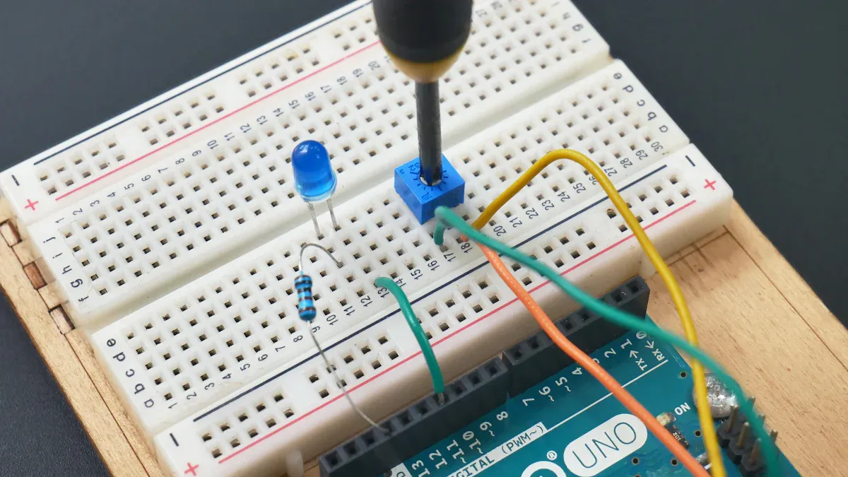
You need a clear circuit diagram before you start connecting your laser module to the Arduino. The diagram shows how each part connects and helps you avoid mistakes. Most laser diode modules have three pins: VCC (power), GND (ground), and SIG (signal). The VCC pin connects to the Arduino 5V pin. The GND pin connects to any Arduino ground pin. The SIG pin connects to a digital output pin, such as pin 8 or 13.
Here is a simple circuit diagram for interfacing a laser diode with Arduino:
[Arduino 5V] ---- [VCC] Laser Module [GND] ---- [GND] Arduino
                          |
                    [SIG] Laser Module ---- [Digital Pin 8] Arduino
Some laser modules only have two pins: VCC and GND. In this case, you control the laser by turning the power on or off. If your module does not have a built-in driver, you must add a current-limiting resistor to protect the laser diode. This resistor keeps the current safe and stops the diode from burning out. For example, a 66k ohm resistor in series with the laser diode can stabilize the current and prevent damage. Always check your module’s datasheet for the correct value.
💡 Tip: Use a breadboard to build your circuit first. This lets you test your setup and make changes easily.
Pin Connections
You must connect each pin of the laser diode module to the right Arduino pin. Follow this step by step process:
Place the laser module on your breadboard.
Connect the VCC pin of the laser module to the 5V pin on the Arduino.
Connect the GND pin of the laser module to a GND pin on the Arduino.
Connect the SIG pin of the laser module to a digital output pin on the Arduino, such as pin 8.
If your module does not have a built-in driver, add a current-limiting resistor between the VCC pin and the laser diode. This resistor protects the diode from too much current.
Double-check the polarity. The anode (+) must go to VCC, and the cathode (–) must go to GND. Some modules have a third pin for the case, which you can leave unconnected unless the datasheet says otherwise.
Laser Module Pin | Arduino Pin | Purpose |
|---|---|---|
VCC | 5V | Power supply |
GND | GND | Ground |
SIG | Digital Pin (8) | Laser ON/OFF control |
You can use jumper wires for easy connections. Make sure the wires fit snugly and do not touch each other. If you use a standalone laser diode, you must use a driver circuit or a constant current source. An LM317 voltage regulator can act as a simple constant current driver. Adjust the current to match your laser diode’s datasheet. Some advanced modules include a photodiode for feedback to keep the power output stable.
⚠️ Alert: Never connect the laser diode directly to power without a current-limiting resistor or driver circuit. This can destroy the diode in seconds.
Double-Check Wiring
Before you power up your circuit, you must double-check all wiring. This step by step check helps you avoid mistakes that can damage your laser module or Arduino.
Make sure each wire goes to the correct pin.
Check that the VCC pin connects to 5V, GND to ground, and SIG to the chosen digital pin.
Look for loose wires or short circuits.
Confirm the current-limiting resistor is in place if your module needs one.
Review the circuit diagram and compare it to your setup.
Make sure the Arduino is not plugged into power while you check the wiring.
🛡️ Safety Note: Always wear laser safety glasses before turning on the laser module. Never look into the beam, even if you think the laser is off.
When you finish these checks, you can safely power up your Arduino and test the laser module. Careful wiring and the right circuit protect your components and keep your project safe.
Arduino Laser Module Code
Code Overview
You can use a simple program to control the laser module with your Arduino. This program lets you turn it on and off at set times. Many laser modules have a control pin that connects to a digital pin on the Arduino. You can also modulate its intensity using PWM, but for most projects, switching the laser on and off is enough.
Here is a table showing how to connect your laser module for this program:
Laser Module Pin | Function |
|---|---|
VCC | Connect to 3V-5V power source (e.g., Arduino 5V) |
GND | Connect to ground |
TTL/Control | Connect to Arduino digital pin (e.g., pin 9) for on/off or PWM control |
Below is a complete program that will blink the laser every second:
const int laserPin = 9;

void setup() {
  pinMode(laserPin, OUTPUT);
}

void loop() {
  digitalWrite(laserPin, HIGH);  // Laser ON
  delay(1000);
  digitalWrite(laserPin, LOW);   // Laser OFF
  delay(1000);
}
This sketch works with most laser diode modules that use a TTL or control pin.
Code Explanation
Let’s look at the code line by line so you can understand how to control the laser module:
const int laserPin = 9;
This line sets pin 9 as the control pin for the laser module.void setup() { pinMode(laserPin, OUTPUT); }
In the setup function, you tell the Arduino to use pin 9 as an output. This means the Arduino can send signals to the laser.void loop() { ... }
The loop function runs over and over. Inside, you usedigitalWrite(laserPin, HIGH);to turn the laser on. Thedelay(1000);command keeps it on for one second. Then,digitalWrite(laserPin, LOW);turns the laser off. Anotherdelay(1000);keeps it off for one second. This cycle repeats, so the laser blinks.
You can change the pin number or the delay times to fit your project. If you want to modulate its intensity, you can use analogWrite() instead of digitalWrite() for PWM control.
💡 Tip: Always use comments in your code. Comments help you remember what each part does and make it easier to fix problems later.
Uploading Code
You need to upload your program to the Arduino before you can control the laser module. Follow these steps:
Download and install the Arduino IDE from the official website.
Connect your Arduino board to your computer with a USB cable.
Open the Arduino IDE and copy the complete program into a new sketch.
Select your board type (like Arduino Uno) under Tools > Board.
Choose the correct COM port under Tools > Port.
Click the Upload button (the right arrow icon) to send the code to your Arduino.
Wait for the “Done uploading” message. Your laser module should now blink on and off.
If the laser does not work, check your wiring and make sure you selected the right board and port. Always test your circuit before soldering any parts. Label your wires and keep your workspace neat for safety.
🛡️ Note: Make sure you wear laser safety glasses before you power up the laser module.
Testing and Troubleshooting
Power On Test
You need to test your setup before you use your laser diode in a project. Start by checking all your connections. Make sure the Arduino is off when you do this. After you confirm the wiring, plug in your Arduino and get ready for the power on test.
Accurate measurement of power output is important during this step. You can use tools like photodiodes or thermopiles to measure the laser’s strength. These tools help you see if the laser diode works as expected. Always wear safety glasses and follow safety rules. Many labs use special equipment to check the laser’s power and keep everyone safe.
A typical power-on test for a laser diode setup includes these steps:
Check the polarity of the laser diode. Make sure the positive and negative pins match the Arduino’s output.
Run parametric tests. These include checking the forward voltage, reverse breakdown voltage, and leakage current.
Use a Source Measure Unit (SMU) if you have one. It can test the diode’s polarity and measure important values.
Compare your results to the safe limits for your laser diode.
If all values are good, the SMU or your test setup will show a pass code.
You can save your test results and use them to sort working and non-working diodes. This process helps you avoid damage and keeps your project safe.
Expected Results
When you power up your Arduino and run your code, you should see the laser diode light up and turn off in a steady pattern. The laser should blink on and off every second if you use the sample code. You can check the Arduino’s digital pins to confirm the system works. For example, pin D10 should switch between high and low states with each loop. Pins D4 and D5 should stay high if you use them for other controls.
You do not need special benchmark numbers for most Arduino projects. The main thing is to see the laser diode light up and fade out as your code tells it to. If the laser stays on or never turns on, you may have a wiring or code problem. Always check the power output with a meter if you want to be sure the laser is not too strong or too weak.
🟢 Tip: If your laser blinks as expected and the Arduino pins behave correctly, your setup is working.
Common Issues
You may run into problems when you connect a laser diode to an Arduino. Many issues are easy to fix if you know what to look for.
Loose or wrong connections can stop the laser from working. Double-check each wire.
Power supply problems can cause the laser to stay off or flicker. Make sure your Arduino gives enough current.
Faulty components, like a broken laser diode or bad jumper wire, can cause trouble.
Wrong pin assignments in your code can keep the laser from turning on. Make sure the pin number in your code matches your wiring.
Overheating can damage the laser diode. If the module gets hot, turn it off and let it cool.
You can use a multimeter to check voltages and currents. Swap out parts if you think something is broken. The Arduino Serial Monitor is a great tool for debugging. You can print messages to see if your code runs as you expect. If you use the Serial Monitor, make sure the baud rate matches your code.
⚠️ Note: If your laser diode does not light up or fades out too quickly, check your wiring, code, and power supply first. Careful testing and troubleshooting will help you find and fix most problems.
Advanced Laser Diode Projects
Laser Tripwire
You can make a laser tripwire for security or games. This project needs a laser diode, a sensor, and an arduino. When something blocks the laser beam, the system sets off an alarm or does something else.
One maker show had a project with a red laser diode aimed at an infrared LED sensor. The arduino checked the sensor’s voltage. If the voltage dropped too low, the alarm went off. The team had problems, like the laser diode breaking during a demo. They fixed it by taking out a mirror and using a direct laser pointer. This made the system work better. Another group used mirrors to bounce the laser beam down a hallway. The arduino counted how many times people broke the beam during games. The results showed that the sensor could act differently if mirrors moved or the room changed. In another project, a keypad let you enter a code to turn off the alarm. This made the system safer and more fun.
🛡️ Tip: Test your laser tripwire in different lights to make sure it always works.
Multiple Modules
You can use more than one laser diode module in bigger projects. This helps you watch for movement in many spots or use different light colors. Using more modules makes your project stronger, but it also brings new problems.
Aspect | Evidence / Data | Explanation / Relevance to Arduino Projects |
|---|---|---|
Electrical Driver Performance | Custom-designed drivers deliver ultra-short current pulses (~8-10 ns) up to 50-60 A at >500 kHz repetition rates | You can control laser diodes at high speed, which is useful for advanced arduino projects. |
Multiplexing Schemes | Alternating Laser Excitation (ALEX) and Frequency-Wavelength Multiplexing (FWM) used to control multiple diodes | These methods let you run several laser diodes at once or in sequence for multi-wavelength setups. |
Advantages | Reduced cost and size; high signal-to-noise ratio (SNR); high frame rates; customizable optical assemblies | Multiple modules help you build compact, fast, and flexible systems with arduino. |
Limitations | Limited wavelength availability; low pulse energy; multi-mode output complicates focusing; potential cross-talk | You may face problems with color choices, focusing, and electrical interference. |
Temperature Control | Arduino-based monitoring keeps diode temperature below 60 °C | You can use arduino to watch and control the temperature, which protects your laser diodes. |
When you use many modules, you need to plan for power and heat. Arduino can help you watch the temperature and stop overheating. Multiplexing lets you switch lasers fast, which is good for science or art projects.
Further Ideas
You can do even more with your laser diode projects by trying new things and adding features. The NicoLase project shows how arduino can control laser diodes in science tools like microscopes. This system uses special shields to control up to seven devices with very fast timing. You can set arduino as a master clock or make it react to outside signals. This lets you make cool patterns and control many lasers and cameras together.
The open-source design means you can change the hardware and software for your needs. You can add remote control for things like moving lenses. Research shows this setup gives you good timing and power control. You can use these ideas for fun projects, like light shows, smart sensors, or remote-controlled optical tools.
💡 Note: Start with a simple project, like a laser driver circuit. This uses a constant-current LED driver, a laser diode, and a heat sink. Watch the temperature to keep your diode safe. As you learn, you can add more features and try harder designs.
You have learned how to connect and control a laser diode with arduino in this tutorial. Always check your wiring and wear safety glasses before you start. Try new ideas, like building a laser tripwire or using more modules. You can change the code or add sensors to make your project unique. Stay safe and keep exploring new ways to use arduino in your next project!
FAQ
How do you power a laser diode module with Arduino?
You connect the VCC pin to 5V, GND to ground, and the signal pin to a digital output. Most modules work with the Arduino’s 5V supply. Always check your module’s datasheet for voltage and current limits.
Can you control the brightness of a laser diode?
Yes, you can use PWM (Pulse Width Modulation) on a digital pin. Use analogWrite() in your Arduino code. This changes the laser’s brightness by adjusting the duty cycle.
analogWrite(laserPin, 128); // Sets brightness to about 50%
What should you do if the laser diode does not turn on?
Check all wiring first. Make sure the code uses the correct pin. Test the power supply. Replace the laser module if it still does not work. Use a multimeter to check voltage at each pin.
Is it safe to use a laser diode indoors?
You can use a low-power laser diode indoors if you follow safety rules. Always wear laser safety glasses. Never point the beam at eyes, mirrors, or shiny objects. Keep the workspace clear.
Can you use any Arduino board for laser diode projects?
Most Arduino boards work with laser modules. Choose a board that supplies enough current for your module. The Arduino Uno, Nano, and Leonardo are popular choices for beginners.
Why do you need a current-limiting resistor or driver?
A current-limiting resistor or driver protects the laser diode from too much current. Too much current can burn out the diode quickly. Always check your module’s datasheet for the right resistor value.
What happens if you connect the laser diode backward?
If you reverse the polarity, the laser diode may not work or could get damaged. Always double-check the wiring before you power up your circuit.
See Also
Master The Process Of Testing Diodes Within Circuits
Step By Step Guide To Accurately Test Diodes
A Comprehensive Look At Integrated Circuits And Parts
