Slew Rate Explained with Simple Calculation Methods
Slew rate shows how fast an amplifier can change its output voltage. You should care about slew rate because slow circuits cannot keep up with quick signals. If this happens, you will see distortion and lose good signal quality. For example, high-frequency audio or video signals need a fast response. If your amplifier’s slew rate is too low, it cannot follow these quick changes. Then, your output will not match your input.
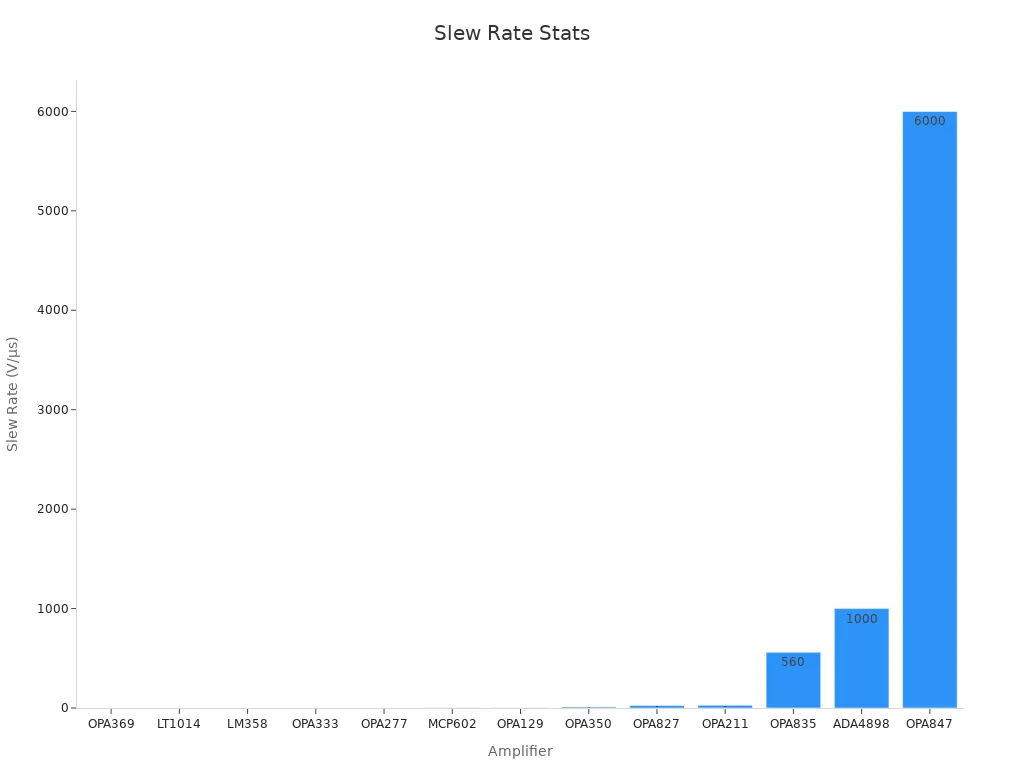
When picking an amplifier, check its slew rate to see if it fits your needs. If you want to compare different amplifiers, look at the table below:
Operational Amplifier | Typical Slew Rate (V/µs) | Typical Application |
|---|---|---|
OPA369 | 0.05 | Low-power portable devices |
LM358 | 0.6 | Battery devices |
OPA350 | 10 | Video amplifiers |
OPA211 | 27 | Audio amplifiers |
OPA847 | 6000 | High-speed communications |
A 1 MHz signal with a 10 V peak needs a slew rate of about 62.8 V/μs. If your amplifier cannot do this, your signal will not stay clean. Modern amplifiers now have features that boost slew rate when needed. This helps you balance speed and power use.
Key Takeaways
Slew rate tells how quickly an amplifier changes its output voltage. This affects how clear the signal is. - Pick an amplifier with a slew rate that fits your signal’s frequency and voltage. This helps stop distortion. - Use this formula: Slew Rate = 2 × π × frequency × peak voltage. It helps you find the speed you need. - Use an oscilloscope to measure voltage change and time. This lets you figure out your circuit’s real slew rate. - If the slew rate is too low, signals get rounded or distorted. This makes audio and video quality worse. - Choose an amplifier with a slew rate about three times higher than you need. This gives you a safe margin. - If the slew rate is too high, it can make noise or cause instability. You need to balance speed and stability. - Good circuit design means checking slew rate, compensation, and feedback. This keeps signals clear.
Slew Rate Basics
Definition
Slew rate shows how fast an amplifier can change its output voltage. It is the highest speed the output voltage can move in a certain time. People measure it in volts per microsecond (V/μs). Engineers use a formula: SR = max |dv_out(t)/dt|. Here, v_out(t) means the output voltage at any time. This number tells you the fastest the output can go up or down. You can test slew rate by sending a step or square wave into the amplifier. Then, you watch how quickly the output rises or falls on an oscilloscope. The input part of the amplifier, called a differential amplifier, sets this speed limit. It does this by controlling how much current charges or discharges the output.
Slew rate is like a speed limit for how fast your amplifier can react to changes in the input signal.
Importance
Slew rate is important because it keeps your signals clear. If the slew rate is too low, the amplifier cannot keep up with quick changes. This makes the signal distorted, especially with fast signals or big voltage jumps. In audio systems, a low slew rate can make music sound bad or unclear. In video circuits, it can make pictures look blurry. Studies and real tests show that when the slew rate drops, distortion gets much worse. One test showed that lowering the slew rate from 60 V/μs to 14 V/μs made distortion 180 times higher. Even if other features are good, a bad slew rate can ruin the signal. Always check the slew rate if you want your output to be clear and correct.
Where It Applies
Slew rate is important in many types of circuits. Here are some common places where it matters:
Operational amplifiers (op amps): Used in audio mixers, filters, and analog computers.
Audio amplifiers: Needed for clean sound in speakers and headphones.
Video amplifiers: Important for sharp images and fast transitions.
Analog-to-digital (A/D) drivers: Ensures fast and accurate data conversion.
Sample-and-hold circuits: Used in digital systems to capture fast-changing signals.
Application Area | Typical Slew Rate Needed | Why It Matters |
|---|---|---|
Audio amplifiers | Prevents sound distortion | |
Video amplifiers | 10–1000 V/μs | Keeps images sharp |
A/D drivers | 5–50 V/μs | Ensures accurate digital conversion |
Sample-and-hold op amps | 100+ V/μs | Captures fast voltage changes |
You should pick a slew rate that fits your circuit’s needs. If it is too low, you get distortion. If it is too high, you might get noise or lose stability. Good design means finding the right balance for your project.
Slew Rate Formula
The Formula
You can find the slew rate of an amplifier by using a simple formula. This formula tells you how quickly the output voltage changes over time. Here is the standard formula:
Slew Rate (SR) = ΔVout / Δt
ΔVout means the change in output voltage.
Δt means the time it takes for that voltage change.
Tip: You can use this formula to check if your amplifier can handle fast signals. If the output cannot change fast enough, you will see distortion.
Variables
Let’s break down the variables in the formula so you know what each part means:
ΔVout: This is the difference between the highest and lowest points of the output voltage during a fast change. For example, if the voltage jumps from 2 volts to 8 volts, ΔVout is 6 volts.
Δt: This is the time it takes for the voltage to make that jump. You measure this in microseconds (μs) or seconds (s). For example, if the voltage changes in 2 microseconds, Δt is 2 μs.
You can use an oscilloscope to measure these values. Set up your circuit, send in a step signal, and watch how fast the output rises or falls. Mark the starting and ending voltage, then note the time it takes to move between them.
Here is a quick example:
Step | What to Measure | Example Value |
|---|---|---|
1 | Starting Voltage | 2 V |
2 | Ending Voltage | 8 V |
3 | Time for Change | 2 μs |
So, ΔVout = 8 V - 2 V = 6 V, and Δt = 2 μs.
Units
You should always pay attention to the units when you work with the slew rate formula. The most common unit is volts per microsecond (V/μs). Sometimes, you might see volts per second (V/s), but V/μs is more useful for most circuits.
V/μs: This means how many volts the output can change in one microsecond.
V/s: This means how many volts the output can change in one second.
Note: Most datasheets for amplifiers list slew rate in V/μs. Always check the units before you compare different devices.
If you want to convert between units, remember:
1 V/μs = 1,000,000 V/s
You can now use the formula, understand the variables, and check the units. This will help you pick the right amplifier for your project and avoid signal problems.
Slew Rate Calculation
Example Problem
Let’s walk through a real-world example so you can see how to calculate slew rate step by step. Imagine you have an operational amplifier (op amp) that needs to handle a 5V peak signal at a frequency of 20 kHz. You want to check if your op amp can keep up with this signal without causing distortion.
You will use the basic formula:
Slew Rate = ΔVout / Δt
This formula helps you find out how quickly the output voltage changes over a certain time. Many engineers use this method to make sure their circuits work well with fast signals. For example, if you want to amplify music or video, you need to know if your amplifier can handle quick voltage changes. If the slew rate is too low, your signal will not look or sound right.
Step 1: Find Voltage Change
First, you need to figure out how much the output voltage changes during the fastest part of the signal. Look at the waveform on an oscilloscope. For a sine wave, the largest voltage change happens at the steepest part of the curve.
If your signal swings from -5V to +5V, the total voltage change is 10V.
If your signal goes from 0V to 5V, the voltage change is 5V.
Simulation data shows that the size of the voltage change directly affects the slew rate. For example:
If you have two signals with the same rise time but one has five times the amplitude, the larger signal will have a slew rate five times greater.
In some simulations, a SlewRateLimiter is set to limit the voltage change to 0.5 volts per second. This helps you see how changing the voltage affects the output.
You can use this information to measure the voltage change in your own circuit. Always check the highest point and the lowest point during the fastest part of the signal.
Tip: The bigger the voltage jump, the higher the slew rate you need.
Step 2: Find Time Interval
Next, you need to measure how long it takes for the voltage to make this change. You can do this with an oscilloscope. Set the sweep rate so you can clearly see the rising or falling edge of the signal. For most op amps, you might use a sweep rate around 500 nanoseconds for a typical 5 V/μs slew rate.
Here’s how you can measure the time interval:
Set up your circuit and connect the oscilloscope probes to the output.
Send a step or square wave into the input.
Watch the output waveform and focus on the steepest part of the edge.
Use the oscilloscope’s measurement tools to mark the start and end points of the voltage change.
Read the time difference between these two points. This is your Δt.
Engineers often use the oscilloscope’s built-in functions to make this easier. Modern scopes can track both voltage and time automatically, so you get accurate results. Matching your measurement setup, including cables and probes, helps you avoid errors.
Note: Accurate time measurement is important. Even small mistakes can change your slew rate calculation.
Step 3: Calculate
Now you have the voltage change and the time interval. You can use the formula to find the answer. Plug your numbers into the formula:
Slew Rate = ΔVout / Δt
Let’s use the example from before. Suppose your output voltage changes by 5 volts in 1 microsecond. Here is how you calculate it:
ΔVout = 5 V
Δt = 1 μs
So,
Slew Rate = 5 V / 1 μs = 5 V/μs
You can also use this formula for other values. For example, if your voltage changes by 10 V in 2 μs, the calculation looks like this:
Slew Rate = 10 V / 2 μs = 5 V/μs
Tip: Always check your units. Make sure you use volts for voltage and microseconds for time. This helps you compare your result with amplifier datasheets.
If you want to check your answer, try using a calculator or the built-in math function on your phone. Write down your numbers, divide the voltage by the time, and you get the answer in V/μs.
Step 4: Interpret Result
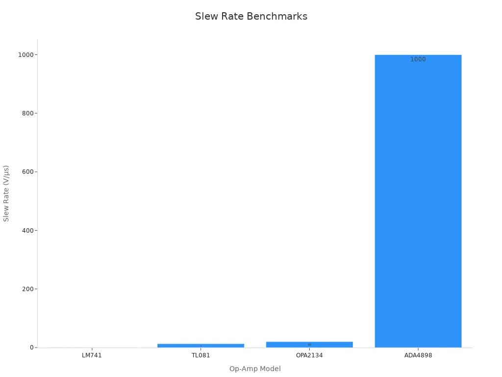
After you calculate the value, you need to see if your amplifier can handle your signal. Compare your result to the typical values for different amplifiers. Use the table below to help you:
Operational Amplifier | Typical Slew Rate (V/μs) | Application Area |
|---|---|---|
0.5 | General purpose, audio processing | |
TL081 | 13 | Audio and video amplifiers |
OPA2134 | 20 | Professional audio equipment |
ADA4898 | 1000 | High-speed communication, radar |
If your calculation shows you need 5 V/μs, the LM741 will not work. It only supports 0.5 V/μs. The TL081 or OPA2134 will work better for your needs. Always pick an amplifier with a value higher than your calculation.
You should not always choose the amplifier with the highest value. High values can cause extra noise or make your circuit unstable. Instead, match your needs to the amplifier’s abilities. Use the formula SR = 2π × frequency × peak voltage to check your requirements for signals like audio or video. Look at distortion plots in the datasheet to make sure the amplifier works well at your signal’s frequency.
Note: Picking the right amplifier keeps your signal clear and your circuit working as expected. Always check both your calculation and the amplifier’s datasheet before making a choice.
Slew Rate in Circuits
Signal Quality
Distortion
When your amplifier cannot keep up with fast changes in the input signal, you will see distortion. This means the output waveform does not match the input. For example, if you send a sharp square wave into an amplifier with a slow response, the output will look rounded or slanted instead of sharp. You might hear this as a muffled sound in audio systems or see it as blurry edges in video signals. Distortion happens most at the steepest part of the signal, like the zero crossing of a sine wave. If the amplifier cannot move fast enough, the signal loses its shape.
Tip: Always check the output waveform on an oscilloscope. If you see sloped or curved edges where there should be sharp ones, your amplifier may have a slew rate problem.
Frequency Limits
Every amplifier has a limit to how quickly it can change its output. This limit sets the highest frequency and largest signal it can handle without distortion. If you use a signal with a high frequency or a large amplitude, you need a faster amplifier. For example, a 0.5 V/μs amplifier takes 4 microseconds to move from 0 to 2 volts. If your signal changes faster than this, the output cannot keep up. You can use the formula:
Required Slew Rate = 2 × π × Frequency × Peak Voltage
If you want to amplify a 20 kHz audio signal with a 10 V peak, you need a required slew rate of about 1.26 V/μs. Always match your amplifier to your signal needs.
Devices Affected
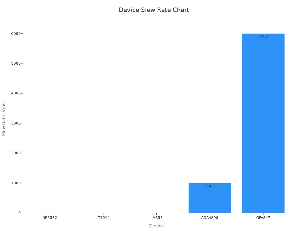
Different devices have different speed limits. Some are made for slow, steady signals, while others are built for fast, sharp changes. The table below shows how various devices compare:
Device | Slew Rate (V/µs) | Typical Application |
|---|---|---|
NE5532 | ~9 | Audio pre-amplifiers, mixing consoles |
LT1014 | ~0.2 | Precision instrumentation, DMMs |
~0.6 | Low-power applications, battery devices | |
ADA4898 | ~1000 | High-speed communication, radar systems |
OPA847 | ~6000 | RF/IF gain blocks, high-speed comms |
You can see that devices like the OPA847 work well for very fast signals, such as in radio or radar. Devices like the LM358 or LT1014 are better for slow signals, such as in battery-powered meters or sensors.
Problem Signs
You can spot slew rate problems by looking for these signs:
The output waveform looks rounded or slanted instead of sharp.
High-frequency signals lose their shape or become distorted.
Audio sounds dull or unclear, especially with fast music or sharp sounds.
Video images show blurred edges or ghosting.
The amplifier cannot reach the full voltage swing at high speeds.
If you notice any of these issues, check your amplifier’s datasheet for its slew rate. Make sure it matches your signal’s needs. Choosing the right device helps you keep your signals clear and accurate.
Applications and Design
Choosing Components
When you pick parts for your circuit, you need to look at more than just the speed of the amplifier. Many experienced users say that other things matter just as much for good audio or signal quality. Here are some points to keep in mind:
Open loop gain, current output, and offset can change how your circuit sounds or works.
The quality of your power supply and the design of your circuit often have a bigger effect than the speed rating alone.
You should choose an op amp with a speed about three times higher than the minimum you need. This helps you avoid problems with slow response.
Picking the fastest op amp is not always best. Very fast parts can cause your circuit to become unstable or start to oscillate.
Improving your power supply or replacing old capacitors can make a bigger difference than swapping op amps just for speed.
Many modern op amps, like the TL07x series, already work well for most audio uses.
Listening tests and direct comparisons in a quiet room help you notice real differences.
Tip: Focus on the whole design, not just one number. Good sound or signal quality comes from a balanced approach.
Matching Requirements
You need to match your component’s speed to your signal needs. If you use a part that is too slow, your signal will get distorted. If you use a part that is too fast, you might get noise or instability. Use this table to help you decide:
Application | Minimum Speed Needed | Common Choices |
|---|---|---|
Audio amplifiers | 3–20 V/μs | TL07x, NE5532 |
Video amplifiers | 10–1000 V/μs | OPA350, OPA847 |
A/D converters | 5–50 V/μs | OPA211, OPA350 |
You should check your signal’s highest frequency and voltage swing. Use the formula from earlier to find the minimum speed you need. Then, pick a part that is about three times faster. This gives you a safety margin and helps prevent distortion.
Note: Matching your part to your needs keeps your circuit clear and stable.
Design Tips
Industry experts share some helpful steps for designing circuits that meet your speed needs:
Use your speed requirement to set the bias currents in your circuit.
Size the input transistors based on these currents.
Apply the phase margin rule to set the gap between the second pole frequency and the gain-bandwidth product.
Use the second pole frequency to choose the right size for key transistors.
Add a nulling resistor in the feedback path to improve phase margin and reduce unwanted effects.
These steps help you balance speed, stability, and sound quality. You can use simple math and interactive tools to make these choices easier. Always test your design with real signals and check the output on an oscilloscope.
Callout: Careful design and testing help you avoid common problems like distortion or instability.
Troubleshooting
Diagnosing Issues
Sometimes your circuit does not work right. The output might look strange or sound bad. If a square wave looks round or audio sounds muffled, the amplifier may be too slow. You can use an oscilloscope to check the output. Watch for signals that do not match the input, especially when things change quickly.
Start by looking at the input signal. Big, quick changes can be hard for the amplifier. When this happens, the input stage current tries to charge the compensation capacitor fast. The output then moves as fast as it can. This speed depends on the input stage current and the compensation capacitance. If you see the output moving at a steady slope, this shows a problem.
Check the feedback loop too. If the loop gain is too high or the phase margin is too low, the circuit can become unstable. This can cause ringing, oscillation, or more distortion. Make sure you know how the feedback factor and op amp gain work together. A stable circuit needs the right mix of speed and control.
Tip: Use the oscilloscope’s tools to compare input and output. Look for any delay or slope that does not match the input.
Solutions
You can fix most problems with a few easy steps. First, make the input step smaller. Smaller changes are easier for the amplifier and keep the output correct. If you need to handle big signals, pick an amplifier with a higher speed.
Next, check the compensation in your circuit. Good compensation helps the amplifier handle fast changes without losing control. Change the compensation capacitor if you need to. This can help balance speed and stability.
You should also control the loop gain. Lowering the loop gain or raising the phase margin can make your circuit more stable. This helps stop oscillation and keeps the output clean. If you use feedback resistors, try changing their values to see if things get better.
Here is a quick troubleshooting checklist:
Check the input signal for big, fast changes.
Measure the output with an oscilloscope.
Compare the input and output waveforms.
Adjust the compensation capacitor.
Change feedback resistor values to control loop gain.
Choose an amplifier with a higher speed if needed.
Problem Sign | Possible Cause | What to Try |
|---|---|---|
Rounded output edges | Speed limit reached | Use faster amplifier |
Oscillation | Low phase margin | Adjust compensation, lower gain |
Distorted audio | Input step too large | Reduce input size, check feedback |
Note: Careful measurement and small changes can fix most problems. Always test your changes and watch the output closely.
Key Points
Recap
You learned what helps an amplifier react fast to changes. The speed of the output voltage is called slew rate. This number shows if your circuit can handle quick signals well. If the amplifier is too slow, you will see distortion in the output. You saw how to use a simple formula to check if your amplifier is fast enough. You also learned how to measure voltage changes and time with an oscilloscope. Picking the right amplifier means checking its speed and making sure it matches your signal.
Here is a table to help you remember the main ideas:
Aspect | Explanation |
|---|---|
Definition | Slew rate is how fast the output voltage changes in an amplifier, usually measured in volts per microsecond (V/µs). |
Typical Values | Most op amps have slew rates near 10 V/µs; low power ones may be about 1 V/µs; high-speed types can go up to 1000 V/µs. |
Causes of Limitation | Things like frequency compensation capacitors, limits on output driver current, and high gain input stages can slow down the slew rate. |
Impact on Performance | If the slew rate is too low, you get distortion, especially with fast or big signals, and the waveform shape changes. |
Slew Rate Asymmetry | Positive and negative slew rates can be different because of how the output stage is built. |
Calculation Formula | Needed slew rate = 2 × π × frequency (Hz) × peak voltage (V), so you do not get distortion. |
Design Considerations | Picking an op amp with the right slew rate is important to stop distortion; some need extra parts for best speed and stability. |
Practical Tools | Slew rate calculators can help you do design math more easily. |
Remember: Always check how fast the amplifier is before using it. This helps you avoid problems with your signal.
Takeaways
Always match the amplifier’s speed to your signal’s needs.
Fast signals or big voltage jumps need a higher speed.
If you see distortion, check if the amplifier is too slow.
Use this formula: Needed speed = 2 × π × frequency × peak voltage.
Measuring with an oscilloscope helps you find real values in your circuit.
Some amplifiers need extra parts to work at their best speed.
Tools like online calculators make design work easier.
Picking the right part keeps your sound and pictures clear.
Tip: Good design starts with knowing your signal and picking the right amplifier for your project.
You know why slew rate is important in your circuits. You can use an easy formula to see if your amplifier works for your needs. This helps stop distortion and keeps your signals clear. Research shows that good ways to calculate and check numbers help prove this. When you build or fix circuits, always remember to think about slew rate. If you want to learn more, look at amplifier datasheets or use online calculators to practice.
FAQ
What does slew rate mean in simple terms?
Slew rate tells you how fast an amplifier can change its output voltage. Think of it as the amplifier’s speed limit for following quick changes in your signal.
Why does a low slew rate cause distortion?
A low slew rate means your amplifier cannot keep up with fast signals. When this happens, the output signal gets rounded or slanted, which causes distortion in sound or images.
How do you measure slew rate?
You can measure slew rate by sending a step or square wave into your amplifier. Use an oscilloscope to see how quickly the output voltage rises or falls. Divide the voltage change by the time taken.
What units do you use for slew rate?
You usually see slew rate measured in volts per microsecond (V/μs). Sometimes, datasheets use volts per second (V/s), but V/μs is more common for most circuits.
Does a higher slew rate always mean better performance?
Not always. A higher slew rate helps with fast signals, but it can also make your circuit noisy or unstable. You should pick a value that matches your needs.
Can you improve slew rate in your circuit?
You can improve slew rate by choosing a faster amplifier or adjusting compensation components. Sometimes, reducing the signal’s size or speed also helps.
What happens if you use an amplifier with too high a slew rate?
If you use an amplifier with a much higher slew rate than needed, you might get extra noise or instability. Always match the amplifier’s speed to your signal’s needs.
Is slew rate important for digital circuits?
Slew rate matters most in analog circuits. In digital circuits, you care more about switching speed and logic levels. However, slow edges in digital signals can still cause problems.
Tip: Always check your amplifier’s datasheet for the slew rate before using it in your project.
See Also
How To Identify And Calculate Errors In Potentiometers
A Guide To Calculating Poles For Amplifier Circuits
Exploring The Operation Of Beat Frequency Oscillators
Improving Amplifier Performance By Knowing Different Gain Types
Key Differences Between SDRAM And Asynchronous DRAM Explained
