How to Test Diodes in Circuit for Accurate Results

Testing diodes in-circuit allows you to diagnose issues without removing components. This approach saves time and effort, especially in complex circuits. To achieve accurate results, you need the right tools and methods. Common tools include:
Curve tracers to visualize current-voltage characteristics.
Functional circuit testing to assess diode performance.
Component testers for basic diode checks.
Temperature testing to monitor voltage drop changes.
Computer-aided testing for automated processes.
Understanding how do you test diodes with these tools ensures reliable troubleshooting and efficient repairs.
Key Takeaways
Checking diodes in a circuit saves time and effort. It helps find problems fast without removing parts.
Use a digital multimeter in diode mode to test easily.
Knowing forward and reverse readings shows if a diode is bad.
Tools like oscilloscopes give more details about how diodes work.
Turn off the circuit and empty capacitors before testing for safety.
Write down your results to spot problems and improve testing.
Test one diode at a time to avoid other parts affecting results.
Check your tools often to keep measurements correct and reliable.
Understanding Diodes and Their Importance

What Are Diodes?
A diode is a small but essential electronic component that allows current to flow in only one direction. It acts as a one-way valve for electricity, ensuring that current moves where it is needed while blocking it from flowing backward. Diodes are made from semiconductor materials like silicon or germanium, which give them their unique properties.
You can think of a diode as a gatekeeper in a circuit. It ensures that electrical signals follow the correct path, preventing damage to other components. This simple yet powerful function makes diodes a cornerstone of modern electronics.
Common Applications of Diodes
Diodes play a critical role in many electronic devices and systems. Their versatility allows them to perform various functions, such as:
Rectification: Diodes convert alternating current (AC) into direct current (DC), which is vital for power supplies in devices like laptops and smartphones.
Signal Demodulation: In communication systems, diodes extract information from modulated signals, enabling audio transmission in radios.
Light Emission: Light Emitting Diodes (LEDs) produce light when current flows through them. You see LEDs in everything from indicator lights to large display screens.
Voltage Regulation: Zener diodes maintain a constant voltage level, protecting sensitive components in electronic devices.
Overvoltage Protection: Diodes safeguard circuits from voltage spikes caused by electrical surges or inductive loads.
Solar Panels: Diodes prevent reverse current flow, ensuring energy efficiency in solar power systems.
Digital Electronics: Diodes are essential in constructing logic gates, which form the foundation of digital circuits.
These applications highlight the importance of diodes in both everyday devices and advanced technologies.
Why Testing Diodes Matters
Testing diodes ensures that they function correctly within a circuit. A faulty diode can disrupt the flow of current, leading to malfunctions or even damage to other components. For example, if a diode in a power supply fails, it may stop converting AC to DC, leaving your device without power. Similarly, a damaged LED may stop emitting light, affecting the functionality of the device it is part of.
By testing diodes, you can identify issues early and prevent costly repairs. Accurate testing also helps you verify that a circuit operates as intended, especially in critical applications like communication systems or solar panels. Whether you are troubleshooting a malfunctioning device or maintaining a complex system, testing diodes is a crucial step in ensuring reliability and performance.
Prerequisites for Testing Diodes in Circuit
Before testing diodes in a circuit, you need the right tools and must follow essential safety precautions. These steps ensure accurate results and protect both you and your equipment.
Essential Tools for Diode Testing
To test diodes effectively, you need specific tools designed for electronic diagnostics. Here’s a list of essential equipment:
Digital Multimeter (DMM): Most modern multimeters include a diode testing function. This tool is ideal for quick and straightforward multimeter testing of diodes.
Oscilloscope: Use this to observe the diode’s waveform and behavior under different conditions.
Signal Analyzer: This tool helps analyze the diode’s frequency response and other characteristics.
Curve Tracer: It plots the current-voltage (I-V) characteristics of a diode, providing detailed insights into its performance.
Power Supply: Apply forward bias voltage and measure the current flow through the diode.
Component Tester: Specialized testers can identify and evaluate various electronic components, including diodes.
Each tool serves a unique purpose, so choose the one that best fits your testing needs.
Safety Precautions for Testing Diodes
Testing diodes in-circuit involves working with electrical components, which can be hazardous if proper precautions are not taken. Follow these safety measures to ensure a safe testing process:
Power Off the Circuit
Always turn off the power supply before testing. This prevents electrical shocks and protects your testing equipment from damage. Working on a live circuit can lead to inaccurate readings and potential harm.
Discharge Capacitors
Capacitors in the circuit can store electrical energy even after the power is turned off. Discharging them is crucial for your safety and the health of your tools.
WARNING: Make sure the capacitor is discharged! This is both for your safety and the continued health of your multimeter.
Neglecting this step can damage the circuitry and pose a risk of electric shock. Use a resistor or a capacitor discharge tool to safely release stored energy.
Use Protective Equipment
Protective gear minimizes risks when working with electrical components. Essential items include:
Insulated gloves to prevent electrical shocks.
A non-conductive work surface to avoid accidental grounding.
An isolated power supply to reduce electrical noise and shock risks.
A fire extinguisher for emergencies, especially when dealing with high currents or voltages.
These precautions create a safer environment for testing and troubleshooting.
By gathering the right tools and following these safety measures, you can confidently test diodes in-circuit while ensuring accurate results.
Step-by-Step Guide for Testing Diodes

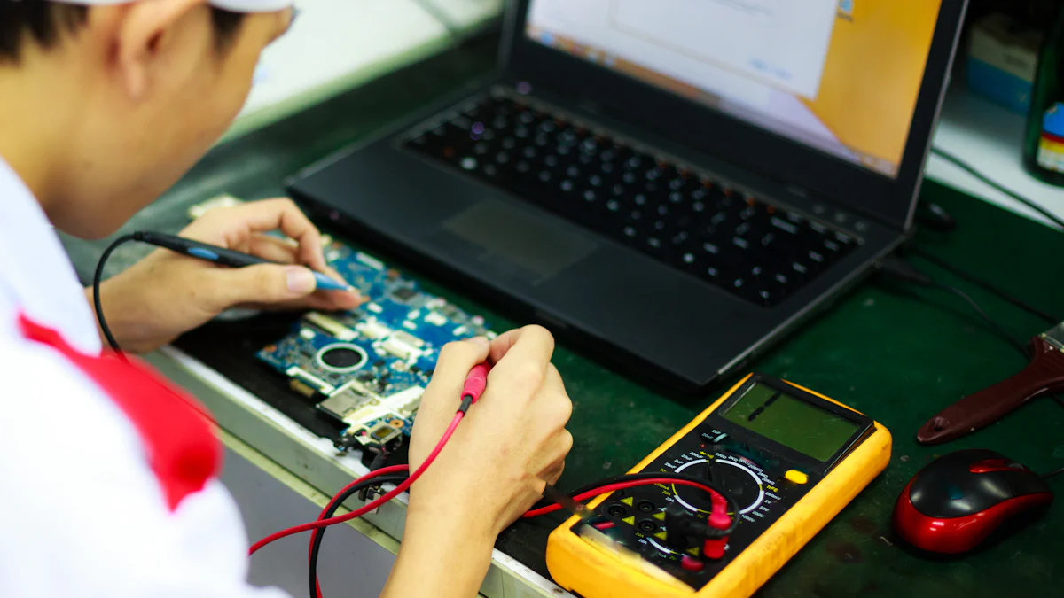
How Do You Test Diodes with a Multimeter?
Setting the Multimeter to Diode Mode
Start by setting your multimeter to the diode test mode. This mode applies a small voltage to the diode and measures the current flow. Locate the diode symbol on your multimeter and turn the dial to select it. If your multimeter lacks this mode, use the resistance mode as an alternative.
Testing Forward Bias
Identify the anode (positive side) and cathode (negative side) of the diode. Place the red probe on the anode and the black probe on the cathode. A functional diode will show a voltage drop, typically between 0.6V and 0.7V for silicon diodes. If the reading is zero or infinite, the diode may be faulty.
Testing Reverse Bias
Reverse the probes by placing the black probe on the anode and the red probe on the cathode. A healthy diode will block current, resulting in an infinite or very high resistance reading. If the multimeter shows a low resistance, the diode is likely damaged.
Using a multimeter is one of the simplest testing methods. It quickly assesses diode functionality by measuring forward and reverse resistances. This tool is ideal for basic diode testing and troubleshooting.
Testing Diodes with an Oscilloscope
Setting Up the Oscilloscope
Turn on the oscilloscope and let it warm up for stable readings. Connect the probe to the oscilloscope and attach the probe’s clip to the diode’s anode and cathode. Adjust the oscilloscope to display a DC voltage scale suitable for the diode’s expected bias voltages, usually between -1V and +1V. Apply a sinusoidal or square wave input to the diode, ensuring the amplitude and frequency match the diode’s specifications.
Interpreting Waveforms
Observe the waveform displayed on the oscilloscope. A properly functioning diode will show a clipped waveform, indicating it conducts in forward bias and blocks current in reverse bias. This visual representation provides more detailed insights into the diode’s performance compared to a multimeter’s numerical readout. Oscilloscopes are especially useful for identifying subtle issues in diode behavior.
Diode Testing Using a Signal Analyzer
Generating Test Signals
A signal analyzer allows you to test diodes in complex circuits. Generate test signals with appropriate frequencies and amplitudes for the diode under examination. This step is crucial for analyzing the diode’s behavior in real-world applications, especially in RF circuits.
Analyzing the Response
Examine the diode’s frequency response, linearity, and harmonic distortion using the signal analyzer. This tool provides detailed insights into how the diode performs at different frequencies. It also detects minor irregularities that could affect circuit performance. While signal analyzers offer advanced testing capabilities, they require careful setup and calibration for accurate results.
Each of these testing techniques has its strengths. Multimeters are quick and straightforward, oscilloscopes provide real-time visual data, and signal analyzers excel in precision applications. By understanding how do you test diodes with these tools, you can choose the best method for your needs.
Overcoming Challenges in Diode Testing
Diode testing in-circuit often presents unique challenges. These obstacles can affect the accuracy of your results and complicate the troubleshooting process. Understanding these challenges and learning how to overcome them will help you achieve reliable outcomes.
Interference from Other Components
When testing diodes in-circuit, surrounding components can interfere with your measurements. This interference often leads to inaccurate readings.
Identifying Parallel Paths
Parallel paths in a circuit can create alternate routes for current, making it difficult to isolate the diode under test. To identify these paths, you can use guarding techniques. Guarding involves isolating the unwanted parallel paths by applying a ground at specific nodes. This method effectively removes those paths from the measurement circuit, allowing you to focus solely on the diode.
Isolating the Diode Under Test
Once you identify parallel paths, isolating the diode becomes essential. Disconnecting one end of the diode or temporarily removing nearby components can help. If physical disconnection isn’t possible, advanced tools like curve tracers can provide more precise results by compensating for interference.
False Readings in Diode Testing
False readings are a common issue during diode testing. These inaccuracies often stem from the influence of other components in the circuit.
Discharging Residual Voltage
Residual voltage in capacitors or other components can distort your readings. For example, surrounding components may lower the forward bias voltage when testing diodes in-circuit compared to out-of-circuit tests. Reverse bias readings can also show unexpected results due to other elements on the board. To avoid these issues, always discharge capacitors before testing. Use a resistor or a discharge tool to safely release stored energy. This step ensures that your measurements reflect the diode’s true condition.
Accessing Hard-to-Reach Diodes
In some cases, diodes are located in tight or inaccessible areas of a circuit. Testing these diodes requires careful planning and the right approach.
Tips for Testing in Tight Spaces
To test hard-to-reach diodes, follow these best practices:
Set up a simple test circuit to apply forward and reverse bias voltages.
Measure the current flow and document the results for future reference.
Discharge capacitors before testing to ensure safety.
Use appropriate personal protective equipment, such as insulated gloves.
Follow proper ESD (Electrostatic Discharge) procedures to protect sensitive components.
Environmental factors like temperature, humidity, and electromagnetic interference can also affect your results. Controlling these variables during testing will improve accuracy. For photodiodes, minimize light exposure to avoid skewed readings.
By addressing these challenges, you can enhance the reliability of your diode testing techniques. Whether you’re isolating a diode, preventing false readings, or working in tight spaces, these strategies will help you achieve accurate results.
Practical Solutions for Accurate Diode Testing
When to Remove a Diode for Testing
Sometimes, you may need to remove a diode from a circuit to ensure accurate readings. In-circuit testing often introduces interference from surrounding components, which can distort your results. Removing the diode eliminates these influences and allows you to test it in isolation. Consider removing a diode in the following situations:
When the circuit has multiple parallel paths that affect the readings.
If the diode is part of a complex network with capacitors or resistors that alter its behavior.
When initial in-circuit tests show inconsistent or unclear results.
Removing a diode might seem time-consuming, but it ensures precise measurements. Always follow proper safety procedures, such as discharging capacitors and powering off the circuit, before removing any component.
Using Advanced Tools for Complex Circuits
For complex circuits, basic tools like multimeters may not provide enough detail. Advanced tools offer deeper insights into diode performance, especially in specialized applications. Here are some tools and their uses:
Dynamic Resistance Measurement: Tracks resistance changes with voltage or current. Use precision source-measure units (SMU) for this.
Noise Figure Analysis: Measures noise added by the diode, crucial for RF circuits. A noise figure analyzer is essential here.
Thermal Impedance Testing: Evaluates how efficiently the diode dissipates heat. Use a thermal imaging camera for this purpose.
Spectral Content Analysis: Examines unwanted frequencies in the diode’s output. A spectrum analyzer is the tool for this job.
Intermodulation Distortion (IMD) Analysis: Detects new frequencies generated by multiple signals. Use signal generators and a spectrum analyzer.
Advanced Curve Tracing: Includes temperature and frequency in I-V curve analysis. An advanced curve tracer is required.
Pulsed I-V Measurements: Tests diode behavior under pulsed conditions. Use pulse generators and an oscilloscope.
These tools provide a comprehensive understanding of diode performance. They are particularly useful for circuits with high-frequency or temperature-sensitive components.
Verifying Results with Multiple Methods
Using multiple testing methods enhances the accuracy and reliability of your results. Each method offers unique insights, and combining them gives you a complete picture of the diode’s performance. For example:
Use a multimeter for quick checks on forward and reverse bias.
Apply a signal analyzer to evaluate frequency response.
Use an oscilloscope to observe real-time waveforms.
This approach addresses challenges like nonlinear behavior and temperature sensitivity. It also helps confirm results when one method shows unexpected readings. By cross-verifying, you reduce the risk of misdiagnosis and ensure the diode functions as intended.
Tip: Always document your findings from each method. This practice helps you track inconsistencies and refine your testing process.
By knowing when to remove a diode, using advanced tools, and verifying results with multiple methods, you can achieve accurate and reliable diode testing. These strategies ensure you get the most out of your testing efforts, even in complex scenarios.
Testing diodes in-circuit offers a practical way to troubleshoot electronic components. To ensure accurate results, you must follow essential practices:
Use multiple testing methods to combine the strengths of different approaches.
Control temperature to reduce variations during testing.
Regularly calibrate your equipment for precise measurements.
Refer to datasheets or consult experts for proper test parameters.
For troubleshooting, follow these steps:
Apply forward bias voltage.
Measure current flow.
Test reverse bias characteristics.
Document your findings.
By applying these techniques, you can save time, improve accuracy, and maintain reliable circuit performance.
FAQ
What is the easiest way to test a diode in a circuit?
Using a digital multimeter in diode mode is the simplest method. Place the probes on the diode’s terminals to measure forward and reverse bias. This quick test helps you determine if the diode is functional or faulty.
Can you test a diode without removing it from the circuit?
Yes, you can test a diode in-circuit. However, surrounding components may affect the readings. If you get inconsistent results, consider isolating the diode by disconnecting one terminal or removing it temporarily.
What does a good diode reading look like?
In forward bias, a good diode shows a voltage drop of 0.6V to 0.7V for silicon diodes. In reverse bias, it should display infinite or very high resistance. Any deviation may indicate a faulty diode.
Why does my multimeter show zero voltage in both directions?
A zero reading in both directions suggests a shorted diode. This means the diode no longer blocks current in reverse bias. Replace the diode to restore proper circuit functionality.
How do you test a diode in a high-frequency circuit?
Use a signal analyzer or oscilloscope for high-frequency circuits. These tools help you observe the diode’s behavior under real-world conditions, such as frequency response and waveform clipping.
What should you do if a diode is hard to access?
For hard-to-reach diodes, use flexible probes or extension leads. If possible, test the diode from accessible points in the circuit. Document your findings to ensure accuracy.
Can temperature affect diode testing results?
Yes, temperature impacts diode performance. High temperatures can lower the forward voltage drop, while low temperatures may increase it. Test diodes in a controlled environment for consistent results.
What tools are best for advanced diode testing?
Advanced tools like curve tracers, signal analyzers, and thermal imaging cameras provide detailed insights. These tools are ideal for complex circuits or applications requiring precise measurements.
Tip: Always calibrate your tools before testing to ensure accurate results.
See Also
Testing Starters: A Guide for Vehicles and Equipment
Essential Tips for Selecting the Right Car Relays
Understanding Circuit Board Components and Their Functions
