Boost circuit vs buck circuit what should you choose
Many people have to pick between a boost circuit and a buck converter when they make electronic projects. The best choice depends on if the project needs to make the voltage go up or down. Voltage and how well the circuit works are both important in this choice. Careful planning helps people choose the best option for their devices.
Key Takeaways
Boost circuits make voltage go up, but buck converters make voltage go down to fit what a device needs. Boost converters are good when a device needs more voltage than the power source gives. Buck converters are best for making voltage lower to keep electronics safe and save power. Both boost and buck converters can work very well, often over 90% efficient, which helps batteries last longer and keeps things cooler. Picking between continuous and discontinuous conduction modes changes how well it works, how big it is, and how much it costs. Boost converters need bigger parts and harder controls to keep power steady, but buck converters are easier and smaller. Buck-boost converters can make voltage go up or down, which helps if the input voltage changes a lot. Think about your device’s voltage needs, how efficient you want it, how much space you have, and your budget to choose the right converter.
Boost Circuit Basics
Definition
A boost circuit is a kind of dc/dc converter. It makes the voltage go higher than what you start with. Engineers use boost converters when a device needs more voltage than the power supply gives. The circuit has an inductor, a switch (often a MOSFET), a diode, and a capacitor. These parts work together to raise the voltage. For example, a boost circuit can take a 3V battery and make it power a 5V device. Many small electronics, like portable gadgets, use boost converters. They help devices keep working as batteries lose power. These circuits can work with voltages as low as 0.5V. They can also go up to many volts, depending on how they are made.
Operation
Principle
Boost converters store energy in an inductor for part of the cycle. Then, they send that energy to the load at a higher voltage. When the switch is on, current goes through the inductor. The inductor stores energy in its magnetic field. The output capacitor gives power to the load during this time. When the switch turns off, the inductor sends its energy through the diode to the load. This makes the output voltage higher than the input. The output voltage depends on the input voltage and how long the switch stays on. The formula U = E / (1 - d) shows how the output goes up as the switch is on longer. Boost converters can work in two main ways. In continuous conduction mode (CCM), the inductor current never drops to zero. In discontinuous conduction mode (DCM), the current does drop to zero. CCM has less voltage ripple and better efficiency but needs a bigger inductor. DCM uses smaller inductors but can have more ripple and lower efficiency.
Components
A boost circuit has some important parts:
Inductor: Holds and moves energy.
Switch (MOSFET): Decides when energy is stored or sent out.
Diode: Makes sure current goes the right way.
Output Capacitor: Makes the output voltage smooth.
Load Resistor: Is the device that gets powered.
Picking the right parts is important for good performance and efficiency. The switch and diode must handle the highest voltage and current. Using low-resistance and fast-switching parts helps cut down on losses. Losses come from resistance in the inductor, switch, and diode. There are also losses from switching and from the inductor’s core. Good parts can make the circuit more efficient. Efficiency is how much output power you get compared to input power.
Use Cases
Boost converters are used when devices need more voltage than the power supply gives. Battery-powered things like smartphones and speakers use boost circuits. They help the devices keep working as the battery runs down. In renewable energy, boost converters help control power from solar panels or batteries. They make sure the voltage stays steady for the grid or storage. For example, a step-up converter in a battery pack keeps the output steady as the battery loses charge. Research shows boost converters can be up to 93% efficient in some cases. This helps batteries last longer and devices work better. DC microgrids and energy storage systems also use boost converters. They help move energy well and keep things running smoothly. These uses show that boost circuits are important for giving steady voltage and high efficiency. That makes them a key part of modern electronics and energy systems.
Pros and Cons
Boost converters have good points and some bad points. Knowing these helps people pick the right circuit for their project.
Pros of Boost Converters
Higher Output Voltage: Boost converters can make a low voltage higher. This helps when batteries lose power over time.
Wide Application Range: Many fields use boost converters. Cars, phones, factories, and solar panels all need them. They give steady voltage to sensors, microcontrollers, and LED lights.
Efficiency: Boost converters can be very efficient in CCM. In this mode, the inductor current does not stop. This works well for steady, strong power needs. Efficiency can reach 93%. This saves energy and makes batteries last longer.
Stable Output: In CCM, boost converters give a smooth voltage. This is important for delicate electronics.
Flexible Design: Boost converters work with many input voltages. They can run on as little as 0.5V. This makes them good for small, portable devices.
Cons of Boost Converters
Component Size and Cost: In CCM, boost converters need bigger and pricier parts. This makes the circuit larger and more costly.
Complex Control: CCM needs more advanced control systems. The circuit must watch the current all the time. This makes the design harder.
Electromagnetic Interference (EMI): Boost converters can cause EMI, especially in DCM. DCM has quick current changes. This can make more EMI and bother other electronics.
Higher Output Ripple in DCM: In DCM, the inductor current drops to zero. This causes more voltage ripple and can wear out the diode faster.
Lower Efficiency in DCM: DCM is better for low or changing power needs. But it is less efficient than CCM. This can waste energy and drain batteries faster.
Tip: Pick CCM for steady, strong power and better efficiency. Pick DCM for low or changing power and smaller, cheaper parts.
Performance Comparison Table
Performance Metric | Continuous Conduction Mode (CCM) | Discontinuous Conduction Mode (DCM) |
|---|---|---|
Application Suitability | Medium to high power, steady load | Low to moderate power, variable load |
Inductor Current Behavior | Never drops to zero; smooth triangular waveform | Drops to zero; trapezoidal waveform with zero-current interval |
Efficiency | Higher efficiency, especially under stable loads | Lower efficiency, especially under heavy or fluctuating loads |
Output Voltage Ripple | Lower ripple | Higher ripple |
Diode Stress | Reduced peak current stress, prolongs diode life | Higher peak current stress, potentially reduces diode lifespan |
Inductor Size & Cost | Larger inductors required, increasing size and cost | Smaller inductors, more compact and cost-effective |
Electromagnetic Interference | Lower EMI due to smooth current transitions | Higher EMI due to abrupt current changes |
Control Complexity | More complex control needed due to continuous current monitoring | Simpler control but with higher ripple current |
Component Size & Cost | Larger, more expensive components | Smaller, more affordable components |
Switching Performance | Stable at higher loads, may have switching losses at light loads | Better efficiency at light loads, unstable at higher loads |
Boost converters can work in both CCM and DCM. CCM gives better efficiency and less ripple. But it needs bigger parts and harder control. DCM uses smaller, cheaper parts and is easier to control. But it has more ripple and lower efficiency. The best choice depends on power, load, and size needs. Boost converters are popular because they balance these good and bad points.
Buck Converters Overview
Definition
Buck converters are a kind of dc/dc converter. They lower voltage from high to low. They use switching to control energy flow. This helps give a steady, lower voltage for devices. Engineers pick buck converters for sensitive electronics. These need power from a higher voltage source. Buck converters work with many input voltages. This makes them useful in lots of devices.
Operation
Principle
Buck converters use a transistor switch that turns on and off fast. When the switch is on, energy goes into the inductor. The inductor stores this energy. When the switch turns off, the inductor sends energy to the output. A diode lets current go one way only. This keeps the output voltage steady. An output capacitor smooths the voltage. This gives devices clean power. Pulse-width modulation controls the switching. It helps keep the output voltage right. Buck converters work in two main modes. In Continuous Conduction Mode (CCM), inductor current never drops to zero. This lowers voltage ripple and allows smaller filters. In Discontinuous Conduction Mode (DCM), inductor current drops to zero sometimes. DCM can be more efficient at light loads. But it may cause more voltage ripple and electromagnetic noise.
Components
A buck converter has some main parts:
MOSFET Switch: Turns on and off to control energy.
Inductor: Stores and sends energy to the output.
Schottky Diode: Stops current from going backward.
Output Capacitor: Makes the output voltage smooth.
Controller: Controls the switching.
Each part affects how well the buck converter works. A low-resistance MOSFET can make it more efficient. Schottky diodes lower voltage drop and switching loss. Ceramic capacitors are good for frequency and reliability.
Use Cases
Buck converters are used when devices need lower voltage than the power supply. They power microcontrollers, sensors, and memory chips in computers and phones. Tablets and cameras use buck converters to lower battery or adapter voltage. Industrial machines use them for control circuits. Cars use buck converters for dashboard electronics and LED lights. They also help in solar power systems. Buck converters manage voltage for storage and sharing power. They are very efficient, often over 90%. This saves energy and keeps devices cool.
Pros and Cons
Buck converters have many good points for electronics. They help engineers make systems that need lower voltage. These converters work well when saving power is important. They lose less energy, so they are very efficient. This makes them great for devices that need to save power and stay cool.
Pros of Buck Converters
High Efficiency: Buck converters can be over 90% efficient. They do this by cutting down on energy loss. Phones and tablets use them to save battery life.
Compact Design: Buck converters are small and fit in tight spaces. Wearables and portable gadgets use them because of their size.
Fast Transient Response: Buck converters react fast to changes in power needs. They keep the output voltage steady even if the device needs more or less power.
Simple Circuitry: Buck converters use fewer parts than other voltage regulators. This makes them cheaper and easier to design.
Stable Output: Buck converters give a smooth voltage. This helps sensitive electronics work well.
Tip: Buck converters are best when input voltage is higher than output voltage.
Cons of Buck Converters
Step-Down Only: Buck converters can only lower voltage. They cannot make voltage go up, so they do not work for every job.
Precise Control Needed: The output voltage depends on how the switch works. Engineers must design the control system carefully to keep voltage steady.
Limited Input Range: Buck converters do not work well with big changes in input voltage. They work best when the input voltage stays close to one value.
Electromagnetic Interference (EMI): Fast switching can cause EMI. This can bother other electronics if not handled.
Thermal Management: Buck converters can get hot when working. Good cooling or heat sinks may be needed for high-power devices.
The table below shows the main good and bad points:
Advantages of Buck Converters | Disadvantages of Buck Converters |
|---|---|
High efficiency from less energy loss | Only lowers voltage, cannot increase it |
Small size for tight spaces | Output voltage needs careful control |
Fast response to power changes | Not good for wide input voltage changes |
Fewer parts, so cheaper and simpler | Can cause EMI from fast switching |
Easier control than other circuits | Needs cooling because it can get hot |
Smooth output voltage | Isolated buck designs are more complex |
Engineers pick buck converters because they work well and are reliable. They must also think about cooling and EMI to get the best results. In real tests, buck converters work fast and keep voltage steady. These features make them a top pick for new electronics.
Boost Regulator vs Buck Converter
Voltage Conversion
A boost regulator makes voltage go from low to high. This is good when a device needs more voltage than the battery gives. For example, a boost converter can use a 3V battery to run a 5V device. Buck converters do the opposite job. They take high voltage and make it lower. Many sensitive electronics use a buck regulator to get safe voltage from a bigger power source.
Buck-boost converters can do both jobs. They can raise or lower voltage as needed. This makes buck-boost converters very useful when power changes a lot. In dc/dc converters, you pick based on which way you need the voltage to go. Boost converters are best for making voltage higher. Buck converters are best for making voltage lower. Buck-boost converters can do both, so they work in many places.
Note: Buck-boost regulator circuits are used in battery devices. These devices may have input voltage that goes above or below what is needed.
Efficiency
Efficiency tells us how much power is used well. High efficiency means less energy is wasted as heat. Both boost converters and buck converters try to be efficient. How well they do depends on how they are made and used.
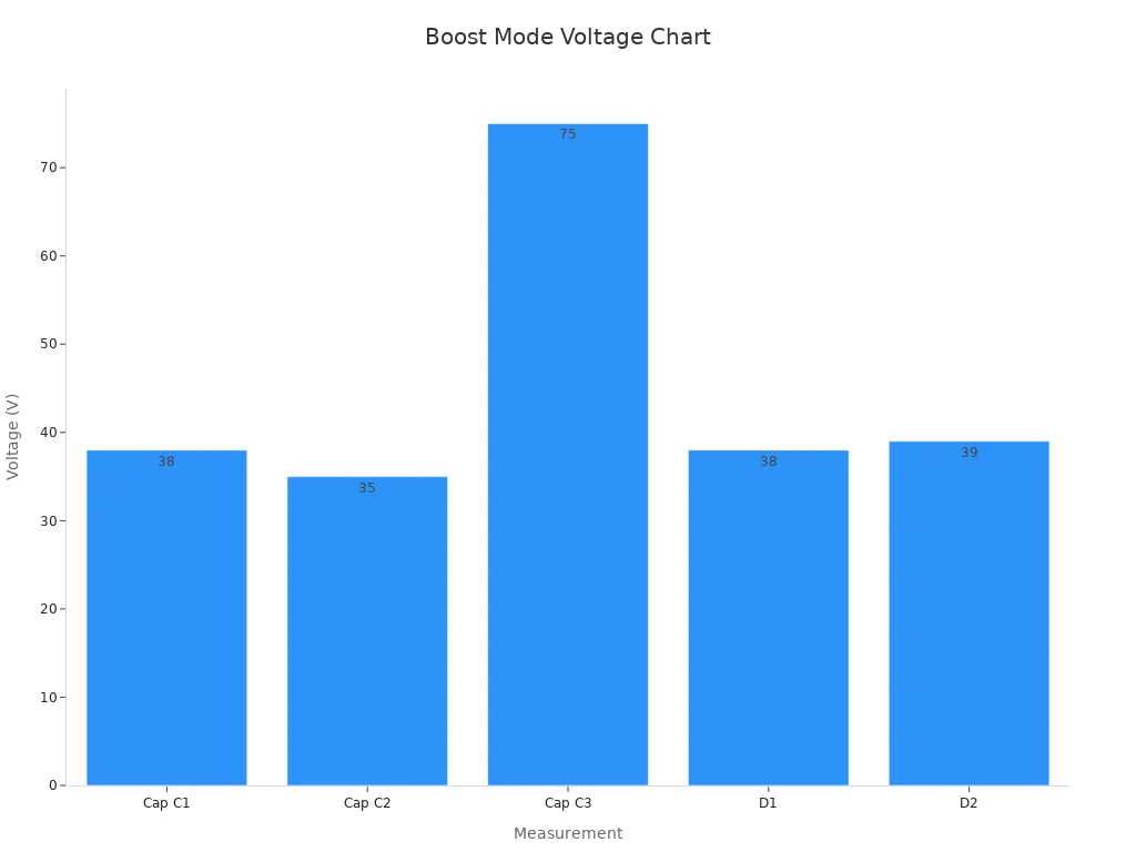
Tests show boost converters can be up to 93% efficient. Buck converters can also be over 90% efficient. The table below shows some test results for boost and buck modes:
Parameter | Boost Mode Value | Buck Mode Value / Observation |
|---|---|---|
L1: 3.1 A | Buck mode diode D3 current ~2.5x boost mode | |
L2: 0.8 A | (higher current leads to higher losses) | |
L3: 0.8 A | ||
Capacitor Voltages (V) | C1: 38 V | Buck mode voltages match what we expect |
C2: 35 V | ||
C3: 75 V | ||
Diode Voltages (V) | D1: 38 V | Buck mode diode voltage matches theory |
D2: 39 V | ||
Power Loss Distribution | N/A | Buck mode diode D3 has more current, so more losses and less efficiency |
Real tests show both boost and buck converters can be very efficient. Boost converters often work better at low power. Buck-boost converters also do well, especially in green energy systems. For example, a buck-boost regulator can switch modes to keep voltage steady and cut down on switching losses. This helps in solar and wind power, where voltage changes a lot.
Efficiency charts show boost and buck-boost converters do well at low power.
Buck converters with similar control can match performance with small changes.
Low quiescent current designs help both boost and buck-boost converters save energy.
Synchronous buck-boost converters often have the best efficiency.
Tip: High efficiency in dc/dc converters saves energy, keeps things cool, and helps batteries last longer.
Complexity
Making a boost regulator or buck converter has different steps. Buck converters need careful math for inductor size, capacitor size, switching speed, and voltage ripple. For example, engineers use formulas to find the right inductor and capacitor. These steps help keep voltage steady and ripple low.
Boost converters have their own hard parts. They must handle higher voltage on switches and diodes. Buck-boost converters are even trickier. They must work for both step-up and step-down jobs. This means more control and careful part choices.
The table below compares how complex each one is:
Complexity Factor | Buck Converter Characteristics | Boost Converter Characteristics |
|---|---|---|
Input Voltage Relationship | Input voltage must be higher than output voltage | Input voltage must be lower than output voltage |
Duty Cycle (D) | Calculated as D = Vout / Vin, affects inductor and capacitor | Duty cycle depends on how much voltage needs to go up |
Inductance (L) | Found using input/output voltage, duty cycle, ripple, and speed | Similar math but for step-up operation |
Capacitance (C) | Based on ripple, speed, and allowed output ripple | Same idea but values change for boosting voltage |
Switching Frequency (fs) | Higher speed means smaller parts but more losses and EMI | Same trade-offs, but parts get more stress |
Component Stress | Switches and diodes feel stress from input voltage and current | Higher voltage stress on switches because of boosting |
Thermal Management | Needed to handle heat from switching and current | More important because of higher voltage and current |
Efficiency Factors | Affected by speed, part quality, load, and heat | Same factors, but step-up losses can lower efficiency |
Control Methods | PWM, current mode, voltage mode keep output steady | Same controls but set for boost operation |
Buck-boost converters need even more care with these things. They must balance both step-up and step-down jobs. This makes designing them take more time and work. Many engineers pick the simplest converter that does the job to save time and money.
Cost
Cost is important when picking a boost regulator or a buck converter. Each one has its own price reasons. Boost regulators need parts that handle higher voltages. These parts, like special switches and diodes, can cost more money. Buck converters use cheaper parts because they lower voltage. This makes buck converters good for low-cost devices.
Engineers also think about the total cost to build and use the circuit. Buck converters are simpler in design. This means less time and money spent on making and testing them. Boost regulators might need extra parts for safety and control. This can make them cost more.
Buck-boost converters can raise or lower voltage as needed. These circuits usually cost more than just boost or buck converters. They use more parts and need careful planning. The table below shows a quick cost comparison:
Converter Type | Typical Part Cost | Design Complexity | Total System Cost |
|---|---|---|---|
Buck Converter | Low | Simple | Low |
Boost Regulator | Medium | Moderate | Medium |
Buck-Boost Converter | High | Complex | High |
Engineers choose the right converter by looking at both part prices and the cost to design and build the whole system.
Applications
Boost regulators, buck converters, and buck-boost converters are used for different things. Engineers pick one based on what the device needs.
Boost regulators are best when a device needs more voltage than the power source gives. For example, LED flashlights and some small speakers use boost regulators. These circuits help keep voltage steady as batteries get weak.
Buck converters are great for devices that need less voltage. Many microcontrollers, sensors, and phone chips use buck converters. They help protect sensitive parts from too much voltage.
Buck-boost converters are special because they can raise or lower voltage. This makes them perfect when the input voltage changes a lot. Solar power systems and battery gadgets often use buck-boost converters. These circuits keep the output steady, even if the battery gets low or the sun is not bright.
Here are some common uses for each type:
Boost Regulator: LED drivers, portable chargers, small solar panels.
Buck Converter: Laptops, tablets, car electronics, home appliances.
Buck-Boost Converters: Power banks, renewable energy systems, car power supplies, and devices that work with many battery levels.
Buck-boost converters give engineers the most choices. They work well in many places where voltage can go above or below what is needed.
Engineers look at what their device needs before picking a converter. They check the voltage, power, and how much the input can change. Buck-boost converters often fix problems in tricky situations. They help devices last longer and stay safe.
Choosing the Right Converter
Application Needs
Each project needs a certain amount of power. Some devices need more voltage than the battery gives. Others need less voltage to keep parts safe. Engineers think about what the device must do before they pick a converter. For example, a portable speaker might use a boost circuit to make the battery voltage higher for louder sound. A robot’s microcontroller might use a buck converter to lower voltage from a big battery. Tablets, cameras, and LED lights all have their own needs. The right converter helps every device work safely and well.
Tip: Make a list of what your device powers. Check if each part needs more or less voltage than your power source.
Voltage Requirements
Voltage is very important to check. The input voltage comes from the battery or power supply. The output voltage is what the device needs to work right. Many battery devices have input voltages that change as the battery drains. For example, a battery might go from 3.0 to 4.2 volts. The device may need a steady 3.3 volts to work well. The converter must keep the output voltage steady, even when the input changes. Engineers use a boost converter if the output voltage must be higher than the input. They use a buck converter if the output voltage must be lower. Some projects use a buck-boost converter when the input can be above or below the output.
Converter Type | Input Voltage vs. Output Voltage | Example Use Case |
|---|---|---|
Boost Converter | Output > Input | Powering 5V device from 3V battery |
Buck Converter | Output < Input | Powering 3.3V chip from 5V supply |
Buck-Boost Converter | Output can be > or < Input | Battery with 3.0–4.2V, output 3.3V |
Always check the lowest and highest input voltage your device will get. Pick a converter that keeps the output steady for all these voltages.
Efficiency Goals
Efficiency tells how much power is wasted as heat. High efficiency means the device stays cooler and the battery lasts longer. Engineers look at many things to reach good efficiency. The on-resistance of the switch (RDS(on)) affects how much energy turns into heat. The diode’s forward voltage drop (Vf) also wastes power. Inductors and capacitors have resistance called ESR, which adds to losses. Switching losses depend on how fast the switch turns on and off and how much charge it moves. Magnetic losses come from the inductor’s core and wires. Control circuits and gate drivers use extra power too. How the converter works matters. Continuous Conduction Mode (CCM) gives better efficiency and less ripple but needs bigger parts. Discontinuous Conduction Mode (DCM) uses smaller parts but wastes more energy. Matching the inductor’s DC resistance with the MOSFET’s RDS(on) helps lower losses. Picking the right duty cycle, inductor value, and switching speed also helps. Engineers often pick bigger inductors and MOSFETs to lower losses, but this can make the circuit larger and cost more. They must balance size, cost, and efficiency for each project.
For best results, set a clear efficiency goal. Choose parts and a converter type that help you reach this goal without making the device too big or expensive.
Size and Budget
How big the parts are and how much money you have are important when picking a boost circuit or buck converter. Every project has limits for space and cost. These limits help decide which converter is best.
Switching frequency is very important. Designers have to make choices:
If the switching frequency is low, the circuit needs bigger inductors. Bigger inductors cost more and use more space. But they help the circuit work better.
If the switching frequency is high, you can use smaller and cheaper inductors. This makes the circuit smaller and costs less. But high frequency can make the circuit less efficient and cause more noise.
The inductor you pick matters too. The inductor changes how the circuit works and how much noise it makes. In buck converters, the average inductor current is the same as the output current. This makes it easier to choose the right control chip and size the parts.
Some new designs use two steps to save space and money. For example, the first step uses a buck-boost stage to make a high middle voltage. This lowers the current in the wires, so there is less heat. It also lets you use smaller and lighter parts. The second step lowers the voltage to what the device needs. This can make the output capacitors smaller and help the circuit react faster to changes.
Designers should always look at how much space is on the circuit board and how much money they can spend before picking a converter. Picking the right switching frequency and inductor size helps balance cost, size, and how well the circuit works.
Real-World Examples
Boost Circuit Applications
Boost circuits are found in many things we use every day. Engineers pick them when a device needs more voltage than the battery gives. For example, a single AA battery has only 1.5 volts. But LED flashlights need more voltage to shine bright. A boost circuit makes the voltage higher so the flashlight works well. Portable speakers also use boost circuits. Their batteries may not give enough voltage for loud music. The boost circuit raises the voltage so the speaker can play louder. Solar garden lights use boost circuits too. The small solar panel charges a battery during the day. At night, the boost circuit makes the voltage high enough for the LED light. Some medical devices use boost circuits as well. Blood glucose meters and hearing aids need steady voltage to work right. The boost circuit helps these devices last longer as the battery gets weak. Small drones use boost circuits because their motors need more voltage than the battery gives. The boost circuit gives the motors enough power to fly.
Boost circuits help devices last longer and work better, even when the battery is low.
Device Type | Why Use a Boost Circuit? |
|---|---|
LED Flashlight | Makes battery voltage higher for brightness |
Portable Speaker | Raises voltage for louder sound |
Solar Garden Light | Powers LED from a low-voltage battery |
Medical Device | Keeps voltage steady for accuracy |
Small Drone | Gives motors the voltage they need |
Buck Converter Applications
Buck converters are used in devices that need less voltage than the power supply gives. Many microcontrollers in computers and tablets use buck converters. The main power supply might give 12 volts. But the microcontroller needs only 3.3 volts. The buck converter lowers the voltage so the chip is safe. Smartphones use buck converters for different parts. The battery gives higher voltage, but the camera, screen, and memory chips need less. The buck converter makes sure each part gets the right voltage. Cars use buck converters too. The car battery gives 12 volts, but dashboard displays and sensors need lower voltage. Industrial machines use buck converters for control systems. These systems need steady, low voltage to work without mistakes. Solar power systems use buck converters to charge batteries. The solar panel may give high voltage, but the battery needs less. The buck converter protects the battery and helps it last longer.
Buck converters make sure sensitive parts get the right voltage, so devices stay safe and work well.
Some common uses for buck converters are:
Powering microcontrollers in computers
Giving voltage to smartphone parts
Running car dashboard electronics
Charging batteries in solar systems
Controlling voltage in industrial machines
Boost circuits and buck converters do different jobs in electronics. The table below shows how they are not the same:
Feature | Boost Converter | Buck Converter |
|---|---|---|
Main Function | Makes voltage go higher | Makes voltage go lower |
Typical Use | Raises power for LEDs, radios | Lowers power for chips, sensors |
Example Device | MP28600 | MP4581 |
You should pick a converter based on what voltage you need and how much energy you want to save. Boost converters work well for step-up jobs and can be more than 92% efficient. Always check what your project needs before you choose. If you have any questions, write them in the comments!
FAQ
What is the main difference between a boost circuit and a buck converter?
A boost circuit makes voltage go up. A buck converter makes voltage go down. Engineers use a boost circuit if a device needs more voltage than the battery gives. They use a buck converter if a device needs less voltage.
Can a boost circuit work with any battery?
A boost circuit works with most batteries. It can make low battery voltage higher for devices. The battery must give enough current for the device to work. Always check what the battery can handle before using it.
Why do engineers care about efficiency in converters?
Efficiency tells how much energy is saved. High efficiency means less heat and longer battery life. Devices work better and stay cooler. Engineers always want high efficiency in their designs.
When should someone use a buck-boost converter?
A buck-boost converter is good when input voltage can be above or below the output. Devices with batteries that change voltage often use buck-boost converters. This keeps the output voltage steady.
Do boost and buck converters make noise?
Both converters can make electrical noise called electromagnetic interference (EMI). Fast switching causes this noise. Good design and filters help lower EMI. Sensitive devices need extra care to stop problems.
Are boost and buck converters safe for sensitive electronics?
Yes, both types can power sensitive electronics safely. They give steady voltage. Engineers must pick the right parts and add protection circuits. This keeps devices safe from voltage spikes.
How do engineers choose the right inductor for a converter?
Engineers look at current, voltage, and switching speed. They pick an inductor that can handle the needed current and keeps voltage ripple low. The right inductor helps efficiency and performance.
See Also
A Complete Guide To Selecting The Right DC-DC Converter
Comparing Bridge And Full Wave Rectifiers For Practical Use
How To Decide Between Electronic And Magnetic Ballasts Effectively
Key Differences Among Common Inverter Chips Explained Clearly
Step-By-Step Guide To Testing Diodes Within Electronic Circuits
